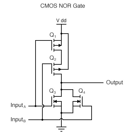
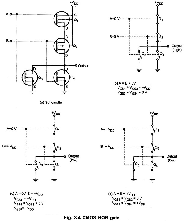
Circuit diagrams are an essential tool for electrical and electronics engineers, providing a simplified way to plan out and illustrate circuit designs. Nor Circuit Diagrams are a specialized type of circuit diagram that uses the Boolean logic operator "nor" as part of the design process.
Nor Circuit Diagrams have become increasingly popular in engineering projects, particularly those involving digital control systems. Unlike more traditional circuit diagrams, nor circuits involve the use of logic gates to create a sequence of events, with each gate acting like a switch allowing a certain amount of electricity to flow through it in a specific order. By using a combination of these switches and logic operators, engineers can create complex, interconnected systems that will ultimately lead to the desired outcome.
The most interesting aspect about Nor Circuit Diagrams is their ability to provide a visual representation of a system's functionality in a much simpler manner than other types of circuit diagrams. This makes them ideal for any engineer, from the novice to the expert. They are also easier to troubleshoot and modify, which can save time and money on a project.
In addition to engineering applications, Nor Circuit Diagrams can also be used in computer programming projects. For example, a programmer may use this type of diagram to illustrate the different steps involved in a program's execution. By providing a diagram that is easy to understand, the programmer can quickly determine the best way to complete their task.
Overall, Nor Circuit Diagrams have revolutionized the engineering field. No longer do engineers need to rely solely on their intuition when designing a project; they now have a simple visual representation of the system they are working on. From creating digital control systems to programming software, Nor Circuit Diagrams offer a convenient and comprehensive way of understanding the inner workings of complex electronic devices.

Cmos Gate Circuitry Logic Gates Electronics Textbook

Logic Gates And Gate Or Nor Nand Truth Table
The Circuit Diagram To Implement Nand Nor And Or Not Logic Scientific

Nor Gate Transistor Logic

Cmos Nor Gate Circuit Working Principle Truth Table
.png?strip=all)
Examples Minimum Nand And Nor Mycareerwise
30 2 Input Nor Gate Scientific Diagram

Logic Nor Gate Electronics Lab Com

Gate Universality Logic Gates Electronics Textbook

Xnor Gate Circuit Diagram Working Explanation

Multiple Input Gates Logic Electronics Textbook

Nor Gate Truth Table Symbol 3input Circuit Diagram Ic

Logic Nor Gate Electronics Lab Com

Transistor Gates

Nor Gate Truth Table With 2 And 3 Inputs Edumir Physics
How Are Nand Gate And Nor Represented With Switches Lamps Quora

Universal Gate Nand And Nor As Gates Electrical4u

32 4 Input Nor Gate Scientific Diagram

Question Using Nor Gates To Make Other Types Of Logic Nagwa

Nor Gate Truth Table Circuit Diagram