Digital clock circuit using ic 555 and 4026 diy electronics projects pic microcontroller pic16f877a based alarm multifunction rechargeable detailed project geek 8051 follow asrelectronicsgeek electronicsrepair electronicsengineering electronicsrepaircenter electronicsprojects engineering life real time with option at89s52 ds1307 rtc interfacing i2c embetronicx 89c51 how to make a simple diagram of quora results page 5 about 16f searching circuits at next gr radio under repository 20361 arduino module nte2062 integrated pmos manualzz de accm application note hacking an seconds display old chips 16x2 lcd schematic scientific garni technology 525 instruction manual manuals serial communication pic16f877 freelancer control seekic com lm8650 homemade auto snooze for clocks available lm8560 eleccircuit light series leds as big 7 segment mc74hc595 uln2003 forum you 4 meter counter school nuts volts magazine adjule resetable 89s52 89c52 in ask hackaday is your tied mains frequency without on the day by anthony boiano tong zhang switch 8 wood block led smart night lights fashion electronic desk timer its working principle ds3234 15 192 consumer book

Digital Clock Circuit Using Ic 555 And 4026 Diy Electronics Projects

Pic Microcontroller Pic16f877a Based Digital Alarm Clock

Multifunction Rechargeable Digital Clock Detailed Electronics Project
Electronics Geek Digital Alarm Clock Circuit Using 8051 Microcontroller Follow Asrelectronicsgeek Electronicsrepair Electronicsengineering Electronicsrepaircenter Electronicsprojects Engineering Life

Digital Clock Circuit Using Ic 555 And 4026 Diy Electronics Projects

Real Time Clock With Alarm Option Using At89s52 And Ds1307 Ic

Rtc Interfacing With 8051 Alarm Clock I2c Embetronicx

Digital Alarm Clock With 8051 89c51 Microcontroller
How To Make A Simple Circuit Diagram Of Digital Clock Quora

Digital Clock Circuit With 8051 Microcontroller

Results Page 5 About 16f Searching Circuits At Next Gr

Radio Alarm Clock Under Repository Circuits 20361 Next Gr

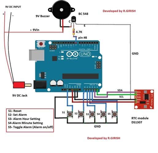
Digital Alarm Clock Circuit Using Arduino And Real Time Module

Real Time Clock With Alarm Option Using At89s52 And Ds1307 Ic

Nte2062 Integrated Circuit Pmos Digital Alarm Clock Manualzz

De Accm Application Note Hacking An Alarm Clock

Digital Clock Circuit With Seconds And Alarm Time Display

Old Clock Chips

Diy Arduino Based Digital Alarm Clock Project Using Rtc Ds1307 Ic And 16x2 Lcd Display
Digital clock circuit using ic 555 and 4026 diy electronics projects pic microcontroller pic16f877a based alarm multifunction rechargeable detailed project geek 8051 follow asrelectronicsgeek electronicsrepair electronicsengineering electronicsrepaircenter electronicsprojects engineering life real time with option at89s52 ds1307 rtc interfacing i2c embetronicx 89c51 how to make a simple diagram of quora results page 5 about 16f searching circuits at next gr radio under repository 20361 arduino module nte2062 integrated pmos manualzz de accm application note hacking an seconds display old chips 16x2 lcd schematic scientific garni technology 525 instruction manual manuals serial communication pic16f877 freelancer control seekic com lm8650 homemade auto snooze for clocks available lm8560 eleccircuit light series leds as big 7 segment mc74hc595 uln2003 forum you 4 meter counter school nuts volts magazine adjule resetable 89s52 89c52 in ask hackaday is your tied mains frequency without on the day by anthony boiano tong zhang switch 8 wood block led smart night lights fashion electronic desk timer its working principle ds3234 15 192 consumer book
