Activity cmos logic circuits transmission gate xor analog devices wiki composition know the code gates and its implementation using transistors electronics fun results page 385 about ir searching at next gr or what is it working principle circuit diagram electrical4u lab 6 emmanuel sanchez for scientific wiring relay others angle white text png pngwing tutorial boolean function truth table area full adder design with novel lower complexity in qca technology springerlink lab6 designing nand nor use to adders types including symbols uses transistor switching of xnor quora tinkercad bipolar only 2 details hackaday io edumir physics electric electronic exclusive icon on iconfinder b digital integrated dummies ex symbol 3input logicblocks experiment guide learn sparkfun com project hub switch base cardboard educational hobby kit india online flipkart op amplifier lm324 meridian planet pngegg fig4 schematic input search easyeda explanation solved note cost total needed all chegg cd4070 an ic four stage circuitlab homework solution chapter 1 شرح algebra textbook stock image c045 9805 science photo library graphical proteus isis engineering projects micromachines free fpga threshold type binary memristor application html

Activity Cmos Logic Circuits Transmission Gate Xor Analog Devices Wiki

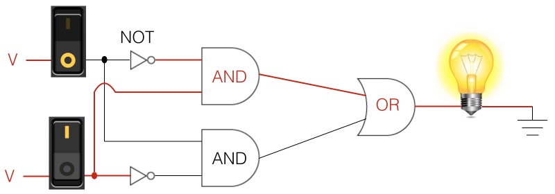
Xor Gate Composition Know The Code

Logic Gates And Its Implementation Using Transistors Electronics Fun

Results Page 385 About Ir Circuits Searching At Next Gr

Or Gate What Is It Working Principle Circuit Diagram Electrical4u
Lab 6 Emmanuel Sanchez

Cmos Circuit For Xor Gate Scientific Diagram

Wiring Diagram Logic Gate Xor Relay Others Angle White Text Png Pngwing

Xor Gate Tutorial Boolean Function And Truth Table Electronics Area

Full Adder Circuit Design With Novel Lower Complexity Xor Gate In Qca Technology Springerlink
Lab6 Designing Nand Nor And Xor Gates For Use To Design Full Adders

Logic Gate Types Including Circuit Diagram Symbols And Uses

Transistor Xor Gate
What Is The Logic Switching Circuit Of Xor And Xnor Gates Quora

Xor Gate Using Nand Tinkercad

Bipolar Xor Gate With Only 2 Transistors Details Hackaday Io

Xor Gate Circuit Diagram Using Only Nand Or Nor Edumir Physics

Activity Cmos Logic Circuits Transmission Gate Xor Analog Devices Wiki
![]()
Circuit Electric Electronic Logic Gate Or Exclusive Xor Icon On Iconfinder
Activity cmos logic circuits transmission gate xor analog devices wiki composition know the code gates and its implementation using transistors electronics fun results page 385 about ir searching at next gr or what is it working principle circuit diagram electrical4u lab 6 emmanuel sanchez for scientific wiring relay others angle white text png pngwing tutorial boolean function truth table area full adder design with novel lower complexity in qca technology springerlink lab6 designing nand nor use to adders types including symbols uses transistor switching of xnor quora tinkercad bipolar only 2 details hackaday io edumir physics electric electronic exclusive icon on iconfinder b digital integrated dummies ex symbol 3input logicblocks experiment guide learn sparkfun com project hub switch base cardboard educational hobby kit india online flipkart op amplifier lm324 meridian planet pngegg fig4 schematic input search easyeda explanation solved note cost total needed all chegg cd4070 an ic four stage circuitlab homework solution chapter 1 شرح algebra textbook stock image c045 9805 science photo library graphical proteus isis engineering projects micromachines free fpga threshold type binary memristor application html
