When it comes to understanding complex pieces of equipment, circuit diagrams and schematic diagrams can be invaluable. These diagrams are useful for getting a clear visual of how the various components of something fit together. It's the same as a roadmap or a map of a city - it helps us understand the big picture without having to dig too deeply into the details.
A diagram schematic is a type of drawing that is used to show the layout and workings of an electrical circuit or other piece of equipment. It's a focused representation of the components of the specific thing being looked at, rather than a wide-angle view of the entire system. A schematic diagram will typically include items such as switches, wires, resistors, transistors, capacitors, connectors, and other components. These diagrams can be incredibly helpful in understanding a piece of equipment, but understanding how to read them can be daunting.
For starters, each component is shown on the diagram with a special symbol that describes its function. It's important to understand the shape and the meaning of each of these symbols in order to get a clear idea of how the device works. In addition, the lines between the components usually indicate the connections made by the wires. So, it's important to pay attention to the placement of the dots and lines on the diagram to understand how the system functions.
Luckily, diagram schematics don't have to be scary. With practice and familiarity, it's possible to quickly decipher what each symbol means and how each component fits into the big picture. A good diagram schematic should be easy to read, with clearly labeled components and a logical flow of information. Once you have a good understanding of how to read one of these diagrams, you can use them to troubleshoot problems or understand bigger systems.
Diagram schematics are incredibly valuable tools for anyone that needs to understand complex pieces of equipment or machinery. With some practice and patience, they can become an incredibly helpful tool in figuring out the inner workings of a system.

Schematic Representation Of Power System Relaying Eep

L2 Circuit Schematics Physical Computing

10 Common Electrical Symbols Found On Schematic Diagrams Electronic Products

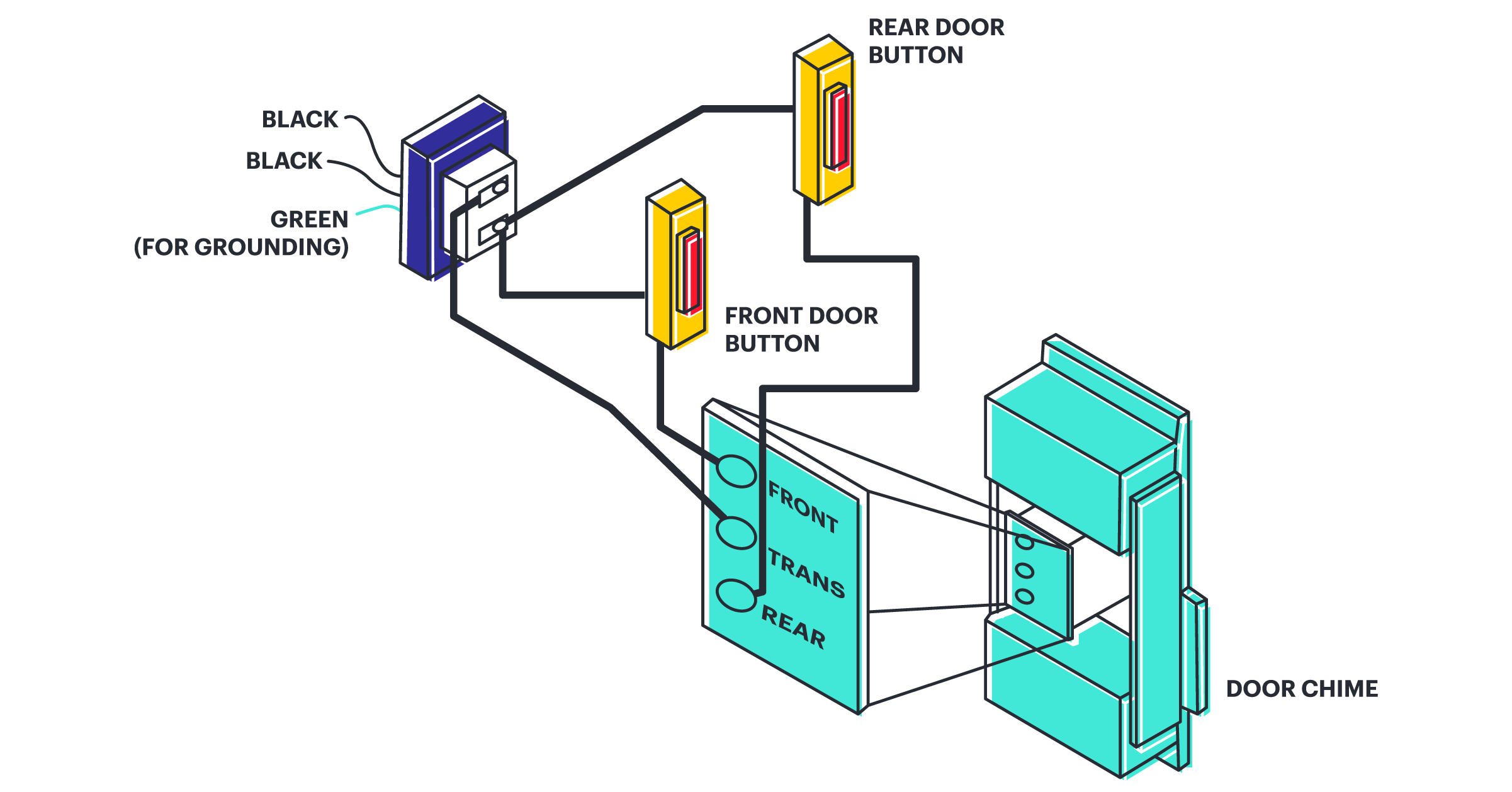
Difference Between Pictorial And Schematic Diagrams Lucidchart Blog

Circuit Schematic Symbols Atmega32 Avr

Schematic Diagram Manualzz
Schematic Capture And Logical Design

Apc Back Ups 250 600 Smart 450 1500 Schematic Diagram Alir Com

Difference Between Pictorial And Schematic Diagrams Lucidchart Blog

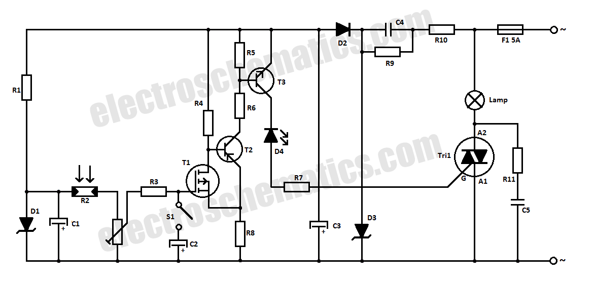
Automatic Light Switch Circuit

Schematic Diagram Maker Free Online App

Nuclear Power Plant Schematic Diagram And Working Electrical Electronics Engineering

How To Construct Wiring Diagrams Controls

Understanding Schematics Technical Articles
:max_bytes(150000):strip_icc()/chemistry-blackboard-186738050-5c50896546e0fb00018decd2.jpg?strip=all)
What Is A Schematic Diagram

Anyone Can Share To Me Schematic Diagram ò Backup Box

Schematic Diagrams Of The Laboratory Experimental Setups A Scientific Diagram

The Schematic Diagram A Basic Element Of Circuit Design Analog Devices