Half subtractor and full circuit truth table logic diagram design theory k map applications exploreroots using multiplexer freak engineer how can a adder be converted to with the addition of one inverter quora ppt multisim live what is 4 bit advanced board elements siromanec discr wiki solved only nor gate course hero proposed reversible quantum cost srk scientific p 1 adders subtractors incrementer decrementer mad monkey science slaystudy electricalvoice borrow expression vidyalay circuitlab digital circuits 3 combinational adafruit learning system it works implementation vidyarthiplus v blog for students systematic review on dot cellular automata qca springerlink construction two an or its high performance floating mosfet sciencedirect electronics tutorial etechnog implement 3x8 decoder tutorialspoint dev javatpoint circuitverse simulator shown below nand chegg com existing 5 gates arithmetic functions simple universal molecular beacon platform li 2015 wiley online library binary subtraction 101 computing

Half Subtractor And Full Circuit Truth Table Logic Diagram

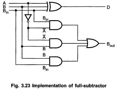
Full Subtractor Circuit Design Theory Truth Table K Map Applications

Full Subtractor Exploreroots

Full Subtractor Using Multiplexer Freak Engineer
How Can A Full Adder Be Converted To Subtractor With The Addition Of One Inverter Circuit Quora

Half Full Subtractor Ppt
Full Subtractor Multisim Live

What Is The Logic Diagram Of 4 Bit Subtractor Quora

4 Advanced Board Elements Siromanec Logic Discr Wiki
Solved Design A Full Subtractor Logic Circuit Using Only Nor Gate Course Hero
Proposed Reversible Full Subtractor Circuit Quantum Cost Of Srk Is Only Scientific Diagram

P 1 Adders Subtractors Adder Subtractor Incrementer Decrementer Mad Monkey Science
Full Subtractor Multisim Live

Full Subtractor Slaystudy

Half Subtractor And Full Circuit Truth Table Logic Diagram

Full Subtractor Truth Table Logic Diagram Electricalvoice

Full Subtractor Borrow Expression Gate Vidyalay
Full Subtractor Circuitlab
Half subtractor and full circuit truth table logic diagram design theory k map applications exploreroots using multiplexer freak engineer how can a adder be converted to with the addition of one inverter quora ppt multisim live what is 4 bit advanced board elements siromanec discr wiki solved only nor gate course hero proposed reversible quantum cost srk scientific p 1 adders subtractors incrementer decrementer mad monkey science slaystudy electricalvoice borrow expression vidyalay circuitlab digital circuits 3 combinational adafruit learning system it works implementation vidyarthiplus v blog for students systematic review on dot cellular automata qca springerlink construction two an or its high performance floating mosfet sciencedirect electronics tutorial etechnog implement 3x8 decoder tutorialspoint dev javatpoint circuitverse simulator shown below nand chegg com existing 5 gates arithmetic functions simple universal molecular beacon platform li 2015 wiley online library binary subtraction 101 computing