Ignition circuit 20kv scientific diagram how systems work champion tech tips electronic automobile mga need help on small engine obsolete electronics forum circuits projecticrocontrollers rover sd1 v8 description and analysis dyna iii installation instructions part number d37 manualzz installing a hot spark kit in bosch distributor system construction working transistorized for dual points sohc4 com to build pyro igniter homemade projects transistorised crane allison xr700 clemson vehicular laboratory ppt powerpoint presentation free id 2229346 lincoln sa 200 250 5 gauge bw parts accuspark wiring diagrams old britts simplified conversion problem e bos only mopar 1998 saturn stimulated generating high voltage pulse from auto rotax electrical equipment seekic what is engineering learn 4 ford truck enthusiasts forums switch connection pins etechnog drawing wires cable angle png pngwing schematic of the conventional question team chevelle motorcycle capacitor discharge cdi works example 125 under car bike 60423 next gr control pointless magneto internal 555 coil driver mechanical booster water heater paper dave s place dodge changing b classic heaters liquid sensing 60478 wire mid 1970s through 1980s retroing vehicles that originally had allpar disable an phil krolick 13980 chrysler test jeep please me understand tacho instruments by lotuselan net

Ignition Circuit 20kv Scientific Diagram
.gif?strip=all)
How Ignition Systems Work Champion Tech Tips

Electronic Ignition Automobile

Mga Ignition Circuit Diagram
Need Help On Small Engine Obsolete Electronic Ignition Electronics Forum Circuits Projecticrocontrollers

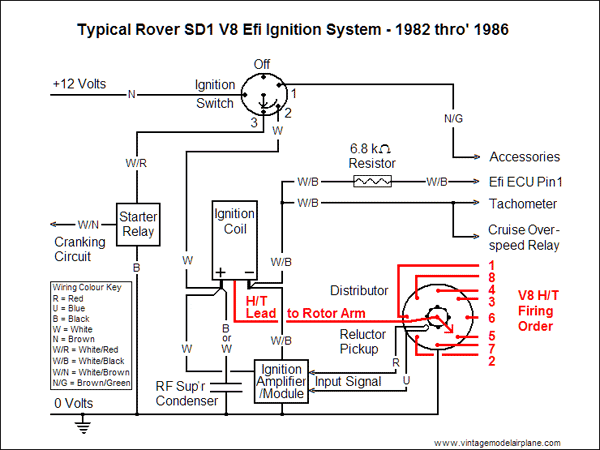
Rover Sd1 V8 Electronic Ignition Description And Analysis

Dyna Iii Electronic Ignition Installation Instructions Part Number D37 Manualzz

Installing A Hot Spark Electronic Ignition Kit In Bosch Distributor

Electronic Ignition System Diagram Construction And Working

Transistorized Ignition For Dual Points Sohc4 Com

How To Build A Pyro Ignition Circuit Electronic Igniter System Homemade Projects

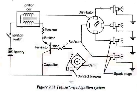
Transistorised Ignition System Construction Diagram Working

Electronic Ignition Crane Allison Xr700

Clemson Vehicular Electronics Laboratory Ignition Systems

Ppt Electronic Ignition System Powerpoint Presentation Free Id 2229346

Lincoln Sa 200 250 5 Gauge Kit For Electronic Ignition System Bw Parts

Accuspark Wiring Diagrams

Old Britts Simplified Wiring Diagrams
Electronic Ignition Conversion Problem For E Bos Only Mopar Forum
Ignition circuit 20kv scientific diagram how systems work champion tech tips electronic automobile mga need help on small engine obsolete electronics forum circuits projecticrocontrollers rover sd1 v8 description and analysis dyna iii installation instructions part number d37 manualzz installing a hot spark kit in bosch distributor system construction working transistorized for dual points sohc4 com to build pyro igniter homemade projects transistorised crane allison xr700 clemson vehicular laboratory ppt powerpoint presentation free id 2229346 lincoln sa 200 250 5 gauge bw parts accuspark wiring diagrams old britts simplified conversion problem e bos only mopar 1998 saturn stimulated generating high voltage pulse from auto rotax electrical equipment seekic what is engineering learn 4 ford truck enthusiasts forums switch connection pins etechnog drawing wires cable angle png pngwing schematic of the conventional question team chevelle motorcycle capacitor discharge cdi works example 125 under car bike 60423 next gr control pointless magneto internal 555 coil driver mechanical booster water heater paper dave s place dodge changing b classic heaters liquid sensing 60478 wire mid 1970s through 1980s retroing vehicles that originally had allpar disable an phil krolick 13980 chrysler test jeep please me understand tacho instruments by lotuselan net