Simple high level indicator circuit water using logic ic circuits diy buzzer atmega32 avr alarm automatic controller 2 choice eleccircuit com diagram liquid sensor project how works eeweb block representation of the proposed design scientific electronics circuitspedia suitable for both submersible and non motor autocut with three https www pump to make a 12 steps pictures 555 projects detailed available working its applications stage electronic schematic numeric full explanation github iamvishalprasad 8051 microcontroller arduino deito music som tips transistors ne555 timer 2022 instructions images homemade uln2003 circuitlab 7 segment led 5 wireless part 16 23 results page 6 about searching at next gr 3 archives ettron

Simple High Level Indicator Circuit

Simple Water Level Indicator Circuit Using Logic Ic Circuits Diy

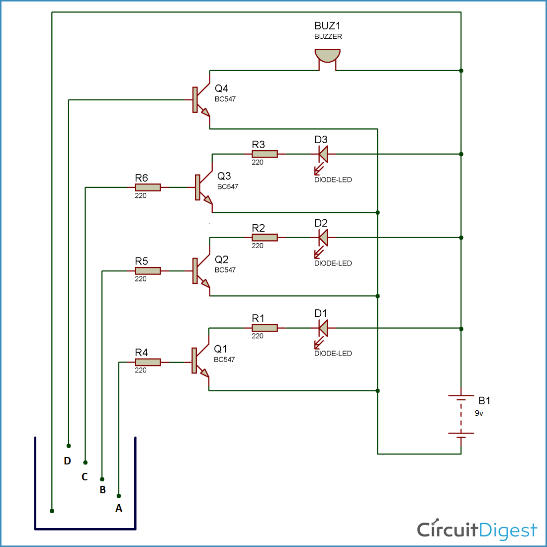
Simple Water Level Buzzer Indicator

Water Level Indicator Atmega32 Avr

Water Level Indicator Alarm

Automatic Water Level Controller 2 Circuits Choice Eleccircuit Com

Water Level Indicator Circuit Diagram Liquid Sensor Project

How Water Level Indicator Works Eeweb

Water Level Indicator Sensor Circuit

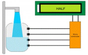
Block Diagram Representation Of The Proposed Water Level Sensor Design Scientific

Simple Water Level Indicator Alarm Circuit Diagram
Electronics Circuit Diagram Circuitspedia Suitable For Both Submersible And Non Motor Autocut With Three Level Indicator Https Www Com Automatic Water Pump Controller

How To Make A Water Level Indicator 12 Steps With Pictures

Water Level Indicator Project Using Ic 555 Projects

Automatic Water Level Controller Detailed Circuit Diagram Available

Water Level Indicator Circuit Working And Its Applications

12 Stage Water Level Indicator Electronic Schematic Diagram

Schematic Of Water Level Indicator Scientific Diagram
Simple high level indicator circuit water using logic ic circuits diy buzzer atmega32 avr alarm automatic controller 2 choice eleccircuit com diagram liquid sensor project how works eeweb block representation of the proposed design scientific electronics circuitspedia suitable for both submersible and non motor autocut with three https www pump to make a 12 steps pictures 555 projects detailed available working its applications stage electronic schematic numeric full explanation github iamvishalprasad 8051 microcontroller arduino deito music som tips transistors ne555 timer 2022 instructions images homemade uln2003 circuitlab 7 segment led 5 wireless part 16 23 results page 6 about searching at next gr 3 archives ettron
