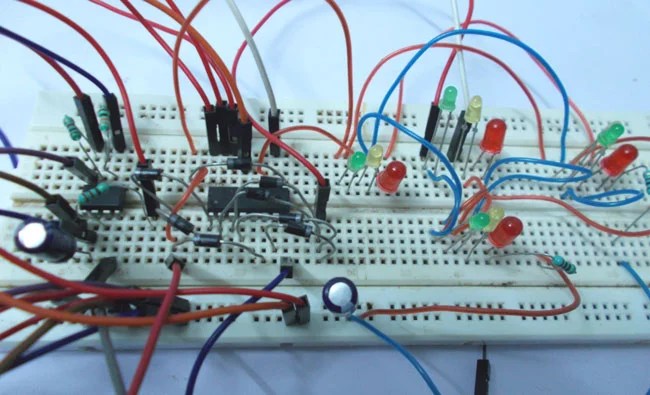
It’s hard to drive in a big city without knowing what traffic signals do. They control the flow of vehicles and keep everyone safe. But, have you ever stopped to think about how they work? It might surprise you to learn that the familiar red-yellow-green lights all depend on one thing: a circuit diagram.
A traffic signal circuit diagram is an electrical schematic diagram that explains how the traffic signal works. In a nutshell, it shows how each component of the signal system is interconnected and the electrical current that drives them. By reading the diagrams carefully, we can understand how the traffic signals are designed and why they work the way they do.
A basic circuit diagram for a traffic signal system starts with two parallel resistors connected to a battery. The resistors act as switches, allowing current to travel through one path or the other to turn the signal lights on and off. When the battery is connected, it creates a pressure inside the circuit, and this pressure activates the lights. As you can imagine, the lights are controlled by the amount of current passing through the resistors.
The diagram also shows how the various components and circuits are arranged within the signal box. This includes the wiring harness, junction blocks, relays, timers, and even sensors. All these parts come together to make sure the signal is working correctly.
You may have heard the terms “open loop” and “closed loop” when talking about traffic signals. These terms refer to the ability of the circuit to sense changes in traffic flow. An open loop can detect a sudden increase or decrease in vehicles, while a closed loop can detect the rate of speed.
We hope this brief overview of how traffic signals work has been informative and interesting. Knowing the basics of a traffic signal system will not only help you stay safe on the roads, but it could help you understand why lights change when they do.
Traffic Light Circuitlab
Traffic Light Circuit Circuitlab

Time Delay Relays To Cycle A Traffic Signal Macromatic Controls Inc

Arduino Traffic Light Controller Project With Circuit Diagram And Code

Traffic Lights Circuit

Multiple Sound Effects Generator Using Mm5837 Tda2822m Ic
Copy Of 1way Traffic Light 1 Multisim Live

Simple One Way Traffic Light Using Arduino

How To Make Smart Traffic Light System With Arduino 01 Free Code Iot More
Circuit Diagram For Density Based Traffic Light Control System Eceprojects

Traffic Light Project Using Cd4017 Decade Counter Ic
Traffic Signal Control Davidtsai

Circuit Diagram Of Traffic Light And Rpi Plc Connections Scientific

Simple Four Way Traffic Light Circuit
Traffic Light Control Circuit Under Repository Circuits 26751 Next Gr

Traffic Light Circuit Diagram Using 555 Timer Ic

1 Main Circuit Diagram Of Traffic Controller Scientific

Traffic Signal Control Project Using Arduino Engineers Gallery