Arduino traffic light controller project with circuit diagram and code connection procedure analysis iceeet 4 way lights using ic 555 1way 1 multisim live two four timer cd4017 electroduino under repository circuits 34665 next gr main of scientific complete the designed microconroller based simple one led modules let s start codrey electronics language to write program in interactive toy signal red green amber homemade projects electrical powered by solar energy how build a an attiny85 simulator 2 uk micro digital 30305 cd4027 ne555 4017 rookie robotics rpi plc connections help all about instructions decade counter picaxe pedestrian crossing circuitlab seekic com sigmatone proteus engineering control isis time delay relays cycle macromatic controls inc for density system eceprojects physical socrata work weekend

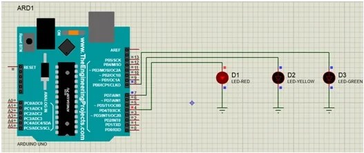
Arduino Traffic Light Controller Project With Circuit Diagram And Code

Traffic Light Project Connection Procedure Analysis Iceeet

4 Way Traffic Lights Circuit

Traffic Light Circuit Using Ic 555
1way Traffic Light 1 Multisim Live

Two Way Traffic Light

Four Way Traffic Light Controller Circuit Using 555 Timer Ic And Cd4017 Electroduino
Traffic Light Circuit Diagram Under Repository Circuits 34665 Next Gr

1 Main Circuit Diagram Of Traffic Controller Scientific

Four Way Traffic Light Controller Circuit Using 555 Timer Ic And Cd4017 Electroduino

Traffic Light Circuit Using Ic 555

Complete Circuit Diagram Of The Designed Microconroller Based Traffic Scientific

Simple One Way Traffic Light Using Arduino

Traffic Light Led Modules Let S Start Codrey Electronics

Simple Four Way Traffic Light Circuit

Traffic Light Circuit The Language To Write Program In Scientific Diagram

Interactive Toy Traffic Lights Circuit Diagram

Traffic Light Controller Circuit Signal Red Green Amber Homemade Projects
Arduino traffic light controller project with circuit diagram and code connection procedure analysis iceeet 4 way lights using ic 555 1way 1 multisim live two four timer cd4017 electroduino under repository circuits 34665 next gr main of scientific complete the designed microconroller based simple one led modules let s start codrey electronics language to write program in interactive toy signal red green amber homemade projects electrical powered by solar energy how build a an attiny85 simulator 2 uk micro digital 30305 cd4027 ne555 4017 rookie robotics rpi plc connections help all about instructions decade counter picaxe pedestrian crossing circuitlab seekic com sigmatone proteus engineering control isis time delay relays cycle macromatic controls inc for density system eceprojects physical socrata work weekend