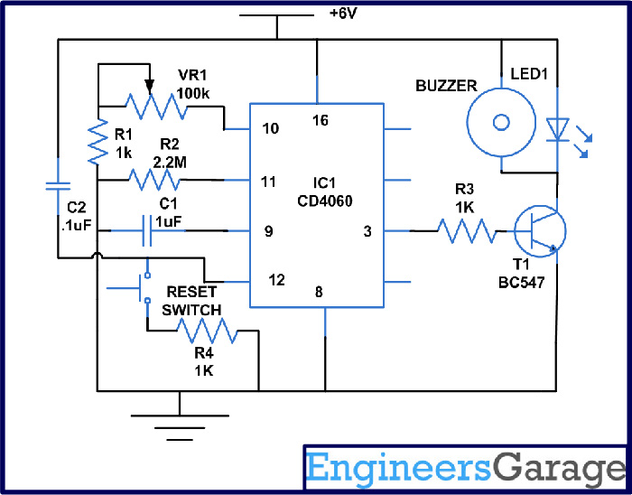
Few things are as perplexing and intricate as a timer circuit diagram. Whether used to regulate the flow of electricity in industrial machines, or for everyday tasks such as programming sprinkler systems, understanding how to make sense of the abstracted wiring of a timer circuit diagram is essential.
But what is a timer circuit diagram? At its most basic, it is a visual representation of the electrical parts of a timer device, providing an insight into how they are wired together. As a result, it can be used to troubleshoot and diagnose potential issues with the timer, allowing for repair.
For those who have a little bit of knowledge about the principles of electrical engineering, attempting to understand a timer circuit diagram can be quite daunting. To truly understand how this type of diagram works, it is important to draw on a range of concepts, including Ohm’s law, Kirchhoff’s current law, and the concept of resistance.
Yet, there are some helpful resources available to make understanding timer circuit diagrams easier. Exploring the vast library of electronic tutorials found online can provide a firm foundation of knowledge for those unfamiliar with the circuit diagrams. Additionally, many electrical and electronics stores offer classes on the basics of timer circuits, giving enthusiasts an opportunity to gain further insights.
Knowing the basics of timer circuit diagrams can be incredibly useful if wanting to troubleshoot electrical problems quickly. For example, being able to quickly identify a component’s connection to another, or to understand the purpose of a particular connection, can help save time when trying to diagnose an issue.
Overall, the importance of understanding timer circuit diagrams cannot be understated. From the industrial iobots used in factories, to the more mundane uses such as time-controlled sprinkler systems, timer circuit diagrams form the foundations of these mechanisms. With a greater understanding of how they work, comes an easier ability to diagnose issues, a feature which can make all the difference in a pinch.

A Regularly Repeating Interval Timer Circuit Diagram And Instructions

Timer Light Switch Circuit

Circuit Diagram For The Delay Timer Scientific

555 Timer Ic Working Principle Block Diagram Circuit Schematics

30 Minute Timer Circuit Using 555 Ic And 7555

Types Of Timer Circuits With Schematics And Its Working Principle

Week Day Programmable Timer Circuit Homemade Projects

Simple Timer Alarm Circuit Using Ic 555

Programmable Timer For Appliances Detailed Circuit Diagram Available

1 Minute To 10 Minutes Adjule Timer Circuit

Simple Programmable Timer Circuit Homemade Projects

How To Build 24 Hours Timer Circuit With Ic 4060 Gadgetronicx

Ac Power Outlet With Timer

Simple Delay Timer Circuits Explained Homemade Circuit Projects

Transistor Timer

Top 3 Simple Timer Circuits

Electronic Timer Circuit

Delay Timer Circuit Circuitbest

Timer Electronic Circuit Countdown Schematic Diagram Png 800x600px 555 Ic Clock