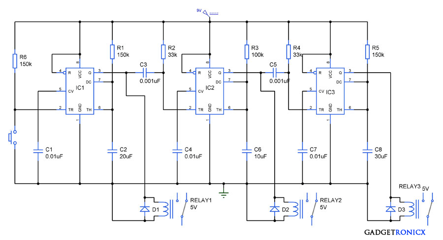
Clock circuits are becoming increasingly popular as a means to control the time delay of electrical systems. A time delay circuit using 555 timer is an important component of this kind of system. This kind of circuit can be used in a variety of applications, such as home lighting, security systems, and motor control.
A time delay circuit diagram using a 555 timer is simple to design and build. It uses a monostable multivibrator, which is essentially a one-shot timer. The timer is set up with two resistors and a capacitor, along with an input trigger switch. When the switch is pressed, the resistor and capacitor provide an initial voltage to the chip, which triggers the output to turn on.
Once the output is triggered, the capacitor starts to discharge, causing the output to stay on until the charge drops low enough that it cannot sustain the output. At this point, the output turns off, and the cycle repeats. This allows the user to program the time delay for whatever application they require.
The use of a 555 timer to build a time delay circuit has some advantages over other alternatives. First, it is a relatively inexpensive solution, making it a great choice for those who need a reliable time delay but are on a tight budget. Additionally, it is easy to configure and use, so even a novice can set up the circuit quickly and accurately.
However, there are some drawbacks to using a time delay circuit diagram using a 555 timer. For one, the maximum time delay that can be achieved with this kind of circuit is limited. Also, if the circuit is not configured properly, the timing can become unreliable. Finally, the 555 timer itself does not last indefinitely, and may need to be replaced periodically.
Overall, a time delay circuit using a 555 timer can be a reliable and affordable way to achieve a precise time delay. If configured correctly, it can be a great choice for a wide range of applications.

Time Delay Relay Circuit Using 555 Timer Ic Electronics Projects

555 Timer Projects For Beginners Diy Electronics

Time Delay Relay Using 555 Timer Ic

How To Build Time Delay Relay Circuit Diagram

Week 1 555 Timer

Simple Timer Alarm Circuit Using Ic 555

5 20 Minuts Timer Circuit Using Ic 555 Eleccircuit Com

Automatic Street Light Project 555 Timer

Low Voltage High Cur Time Delay Circuit Diagram And Instructions

How To Build A Delay Before Turn On Circuit With 555 Timer

Sequential Process Control With Time Delay Using Ic 555 Gadgetronicx

On Delay Timer Circuit Diagram With Relay Using Capacitor

Time Delay Circuit Using 555 Timer

Electronic 555 100

On Delay Timer Circuit Diagram With Relay Using Capacitor

555 Timer And Working Electrical4u

Common Mistakes When Using A 555 Timer

Long Duration Timer Circuit Using 555 Ic

Simple Time Delay Circuit Diagram Using 555 Timer Ic