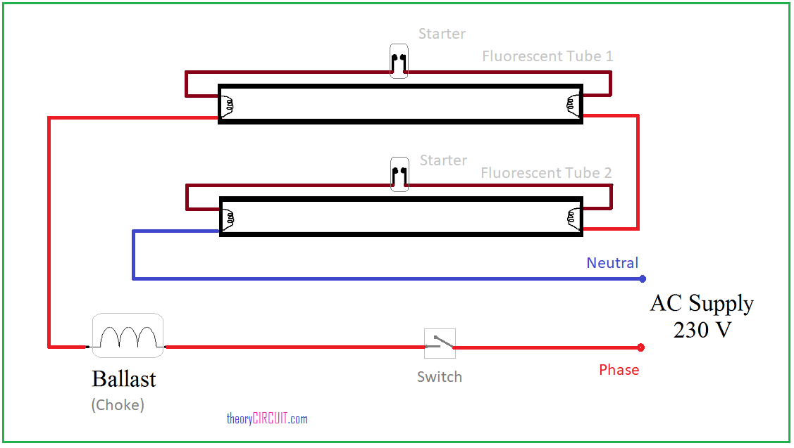
Test light circuit diagrams are essential tools used by electricians and auto mechanics to diagnose issues in a circuit. Without a visual representation of the circuit’s electrical wiring, diagnosing problems can be a time consuming, frustrating process.
A test light is a device used to check the functionality of an electrical circuit. It consists of a wire with a bulb or LED on the tip. By connecting one end of the wire to ground and the other to the circuit, the test light will illuminate if voltage is present. By using the right diagram, you can easily pinpoint the issue.
The first step in troubleshooting an electrical circuit is finding a test light circuit diagram. This diagram will show the different components of the circuit and how they are connected. Test light circuits generally include a light bulb, a power source, and a switch that connect the power source to the load. When an issue occurs in the circuit, components will become either overloaded or disconnected. Diagnosing these issues without a test light circuit diagram can be difficult.
To save time, consider downloading an online test light circuit diagram. Many websites offer diagram templates for free, giving you access to high-quality diagrams quickly. Once you have your diagram, you’ll need to know how to read it. Test light circuit diagrams are divided into several categories including power, input, and output. Knowing which category each component belongs in will help you identify the issue quickly.
By following the simple steps outlined above, you should be able to identify any issues in your electrical circuit. Test light circuit diagrams are vital tools for resolving electrical problems efficiently and correctly. With a little patience and practice, you too can become a master of test light circuit diagnostics.

Sdy Jim S Home Page Aircooled Electrical Hints

10 Automatic Emergency Light Circuits Homemade Circuit Projects

Miller Igbt Mosfet Tester 156114 User Manual Manualzz

How To Read Car Wiring Diagrams Short Beginners Version Rustyautos Com

Double Light Circuit Diagram

Dc Circuits Self Test 2 Physics

Lighting Circuit Diagrams For 1 2 And 3 Way Switching

Backup Lamp Circuit Diagram

Lighting Circuit Diagrams For 1 2 And 3 Way Switching

Basic Ammeter Use Worksheet Electricity

Electrical Installation Testing Procedures Your Guide

Parking Brake Warning Light Circuit
3 Way And 4 Wiring Diagrams With Multiple Lights Do It Yourself Help Com

Wiring Diagram A Comprehensive Guide Edrawmax Online

Electric Circuit Diagrams Lesson For Kids Transcript Study Com

How To Use A Test Light For Automotive Electrical Problems

Push To Test Circuit For Leds Vaf Forums

How To Find An Open Circuit In A Car S Electrical System Axleaddict
Cat No 682083 Emergency Lighting Test Switch Trade
