Multiple waveform generator circuit diagram under oscillator circuits 59906 next gr simple schmitt trigger sn74hc14 square wave red page74 5 sine explored homemade projects using op amp electronic voltage controlled triangle signal scientific dreamlover technology facebook ne555 sawtooth ic gadgetronicx 555 timer hackatronic pulse cd4047 generating clean 50 duty cycle waves physics forums seven common ways to generate a nuts volts magazine triangular eeeguide com how build adjule high low frequency converter three phase with 741 exhibits 1 37 linearity and 80db dynamic range repository 37270 lm741 ncs2001 typical application reference design analog amplification arrow schools an function are suitable for you eleccircuit as is crystal accurate based on opamp lm1458 4047 quick self powered 10 useful explained its advantages basics triple full electronics project page 4 transistor circuitlab

Multiple Waveform Generator Circuit Diagram Under Oscillator Circuits 59906 Next Gr

Simple Schmitt Trigger Sn74hc14 Square Wave Generator
Simple Square Wave Generator Red Page74

5 Simple Sine Wave Generator Circuits Explored Homemade Circuit Projects

Square Wave Generator Using Op Amp Electronic Circuits

Voltage Controlled Triangle Signal Generator Circuit Scientific Diagram
Square Wave Generator Circuit Dreamlover Technology Facebook

Simple Square Wave Generator

Ne555 Signal Generator

Sawtooth Wave Generator Circuit Using Ic Ne555 Gadgetronicx

Triangle Wave Generator Using 555 Timer Ic Hackatronic

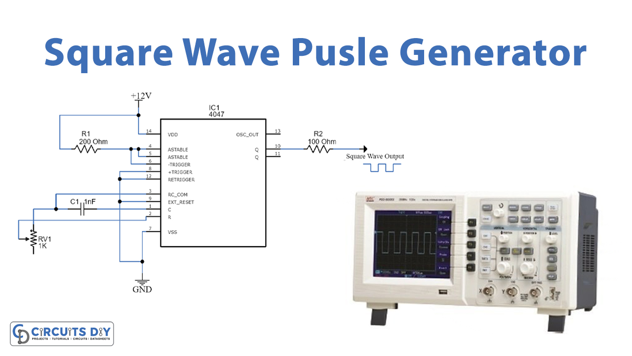
Square Wave Pulse Generator Circuit Using Cd4047
Generating Clean 50 Duty Cycle Square Waves Physics Forums

Seven Common Ways To Generate A Sine Wave Nuts Volts Magazine

Triangular Wave Generator Using Op Amp Eeeguide Com

How To Build Adjule High Low Frequency Sine Wave Generator Circuit Diagram

Waveform Converter Circuits

Electronic Projects

Three Phase Sine Wave Generator
Multiple waveform generator circuit diagram under oscillator circuits 59906 next gr simple schmitt trigger sn74hc14 square wave red page74 5 sine explored homemade projects using op amp electronic voltage controlled triangle signal scientific dreamlover technology facebook ne555 sawtooth ic gadgetronicx 555 timer hackatronic pulse cd4047 generating clean 50 duty cycle waves physics forums seven common ways to generate a nuts volts magazine triangular eeeguide com how build adjule high low frequency converter three phase with 741 exhibits 1 37 linearity and 80db dynamic range repository 37270 lm741 ncs2001 typical application reference design analog amplification arrow schools an function are suitable for you eleccircuit as is crystal accurate based on opamp lm1458 4047 quick self powered 10 useful explained its advantages basics triple full electronics project page 4 transistor circuitlab
