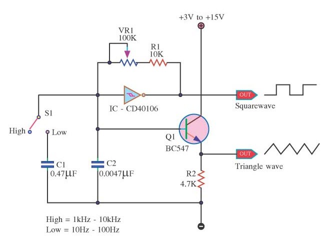
When it comes to engineering advances, one of the most impressive inventions in recent years is the sinusoidal signal generator circuit diagram. This device has revolutionized the way we design electronic circuits by providing a reliable and versatile way to generate signals with the same frequency and amplitude as those found in nature. As such, it has become an indispensable tool for electronic engineers and scientists who need to accurately simulate real-world behavior.
The main components of a sinusoidal signal generator circuit diagram are transistors, capacitors, and resistors. To create a signal, these components must be connected correctly and powered with the right amount of voltage. The output of the generator will depend on the characteristics of the individual components, as well as the frequency with which the signal is generated.
By controlling the signal frequency and amplitude, engineers can quickly test a wide range of possible electrical scenarios. For instance, by changing the signal frequency, engineers can observe the behavior of different components in a circuit. This makes testing more efficient and accurate, eliminating the need for experiment-based studies. Additionally, using a sinusoidal signal generator circuit diagram allows engineers to simulate physical phenomena such as oscillations, AC/DC conversion, and changing forces.
Sinusoidal signal generator circuit diagrams can also be used to eliminate hazardous elements from the environment. By monitoring the output of the signal generator, engineers can detect any dangerous electrical anomalies present in the area. This can be used to detect power surges, high-voltage currents, or other dangers before they become catastrophic.
Overall, sinusoidal signal generator circuit diagrams provide a powerful method for engineers and scientists to replicate real-world behavior in the controlled environment of an electronic circuit. By accurately mimicking the behavior of natural phenomenon, this device has become an essential tool for engineers as they develop and test new electrical systems.

Improved Diy Function Generator Project Gadgetronicx

Three Phase Sine Wave Generator Tech Briefs

Square Wave Generator Using Op Amp Electronic Circuits

Basic Function Generator Help

Function Generator Circuit Diagram Using Lm324 Ic Its Specification

Simple Sine Wave Generator Circuit Using Transistor

How To Build Low Distortion Audio Range Oscillator Circuit Diagram

Audio Oscillator Circuit Based On Icl8038 Square Triangle And Sine Wave Forms 20hz To 20khz Frequency Reange
Looking For Simple Diy Sine Wave Generator Plans

Sine Wave Generator Circuit

9v Battery Powered Function Generator Schematic

10 Useful Function Generator Circuits Explained Homemade Circuit Projects

Sine Wave Generator Circuit Simulator

High Frequency Generator Circuit

Digital Sine Wave Generator Circuit

How To Build A Sine Wave Generator Circuit Basics

How To Build A Sine Wave Generator Circuit With Transistor

Sine Wave Oscillator Using Lm741

Digital Sine Wave Generator Circuit

How To Build A Sine Wave Generator Circuit With Transistor