If you are looking for reliable ways to control motors and other loads in your home, a single phase contactor schematic diagram is the answer. This diagram outlines how a contactor works to enable you to turn a device on and off in your home.
The basic anatomy of a contactor consists of an electromagnet surrounded by a coil of wire. When energized, the electromagnet forms an electromagnetic field that attracts a metal armature, which then closes a set of contacts. This ‘closed’ circuit enables you to power up or shut down whatever device you’re controlling.
A single phase contactor schematic diagram is based off of this simple concept. The diagram will show you the various components of the contactor and how they interact with each other. It will also specify what type of contactors are compatible with the device that you are connecting.
Rather than having to replace entire motor control panels, you can now easily replace individual contactors. You no longer have to worry about power interruptions, as a contactor will reduce the chance of them occurring. They also provide safety features like undervoltage protection and current overload protection.
A single phase contactor schematic diagram is extremely useful, especially if you are dealing with more complex motor control systems. It helps you understand how any given contactor works and ensures you have the correct model for the job. Plus, it simplifies your troubleshooting if something does happen to go wrong.
Whether you are looking for a way to effectively control motors and other loads in your home or are working with more complex motor control systems, a single phase contactor schematic diagram will be your best friend. It provides you with a better understanding of the inner workings of a contactor while providing you with the peace of mind that comes with knowing you have the right model for the job.

Figure F 1 Wiring Diagram Single Phase
A Sketch Of The Electromagnetic Contactor B Magnetic Scientific Diagram

Contactor Construction Working Principle Types And Differences

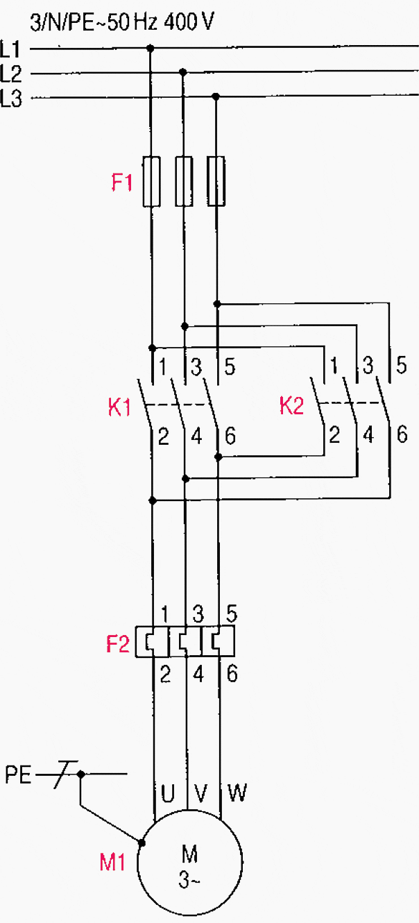
Main And Auxiliary Circuit Diagrams Of Switching Three Phase Motors Via Contactor Directly Eep

Main And Auxiliary Circuit Diagrams Of Switching Three Phase Motors Via Contactor Directly Eep
Eee Tutors Three Phase Motor Run Single Supply How To 3 In Line Facebook By Controlling

Start Stop Circuit What They Are Where And How To Wire
Block Diagram Of The Automatic Changeover Switch Scientific
What Happens If The Three Voltages In A 3 Phase Circuit Do Not Have Difference Quora

Contactors And Relays Construction Operation
Jk Switchgear Single Phase Motor Wiring Diagram Facebook

To Make Test The Working Of Single Phase Preventer Using Contactor Control Free Electrical Notebook Theory And Practical

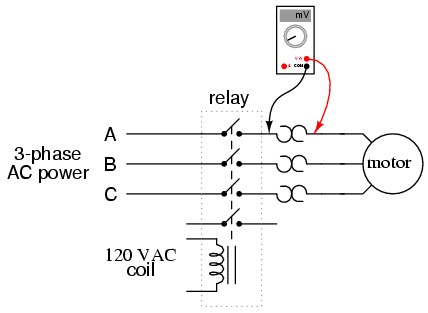
Motor Circuits And Control Applied Electricity

Chapter 4 Electrical Symbols And Diagrams Language Of

Main And Auxiliary Circuit Diagrams Of Switching Three Phase Motors Via Contactor Directly Eep

Motor Circuits And Control Applied Electricity

Electricalonline4u Images For Free
Single Phase Motor Connection Diagram And Wiring Procedure Etechnog


