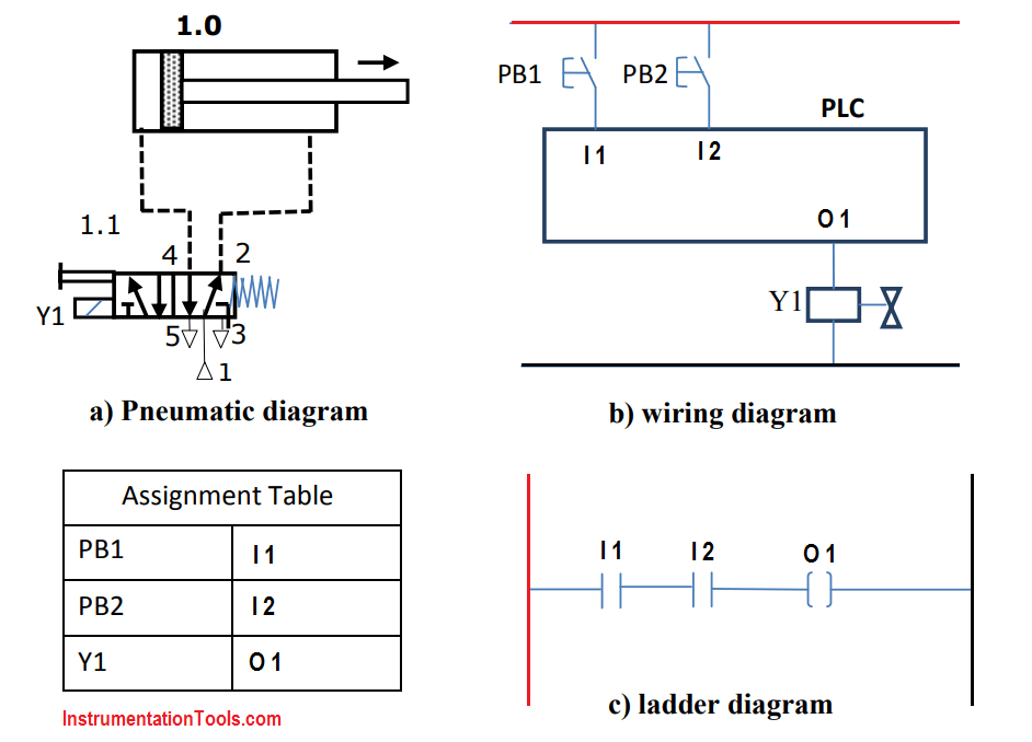
Pneumatic systems are rapidly becoming one of the most popular methods to power industrial machinery. Thanks to their simplicity and low cost, they have become an essential part of modern engineering.
A simple pneumatic circuit diagram is a schematic representation of the air pressure systems used in factories today. It is a basic map that shows the flow of air, as well as its connections to various components. Learning how to read these diagrams is essential to understanding how pneumatic systems work.
So, what does a simple pneumatic circuit diagram look like? Generally, the diagram will show all the major components connected to each other, such as the air compressor, air tanks, valves, and cylinders. These components are connected with lines that indicate the type of connection – either direct or via a hose. Additionally, arrows show the direction of air flow.
In order to understand how a pneumatic system works, it is important to know the basics of pneumatics. Pneumatic systems use compressed air to power machines, and the air is moved from one component to another using valves and actuators. The air is then released into the machine to do the necessary work.
Understanding a pneumatic circuit diagram is a great first step in understanding and troubleshooting pneumatic systems. With a good grasp of the fundamentals of pneumatics and practice with reading diagrams, anyone can quickly become proficient in understanding and maintaining a pneumatic system.
If you need help getting started with pneumatic circuit diagrams, there are plenty of resources available online. There are tutorials available, as well as videos and books that can help explain the basics of pneumatic systems. With enough practice, you will be able to quickly interpret pneumatic diagrams and make the right decisions when it comes to operating and maintaining your pneumatic system.

Direct And Indirect Control Of Single Acting Double Air Cylinders Motors Mechanical Engg Diploma Simple Notes Solved Papers S

Basic Information On Pneumatic Systems E Blog

Plc Pneumatic Circuit Control Programming System
Models Sun Hydraulics

Tutorial 1 How To Construct A Pneumatic Circuit Of Direct Control Single Acting Cylinder Using Festo Fluidsim 3 6 Steemit

The Schematic Diagram Of Electro Pneumatic Circuit In Hsm Scientific

Mechanical Engineering Pneumatic Tutorial Problems

Pneumatic Actuation Circuit Matlab Simulink

Pneumatic Circuit Diagrams Learnchannel Tv Com
The General Design Of A Pneumatic System And Its Components

Hydraulics Pneumatics Ppt Online

Draw And Explain Pneumatic Meter In Circuit To Control Of Sd Extension Mechanical Engineering Simple Notes Solved Problems S

Electro Pneumatic Circuit Diagram Scientific

Designing Safe Pneumatic Circuits Manufacturingtomorrow

Reading Fluids Circuit Diagrams Pneumatic Examples
Unit 6 Hydraulic And Pneumatic Circuits

Pneumatic Systems
