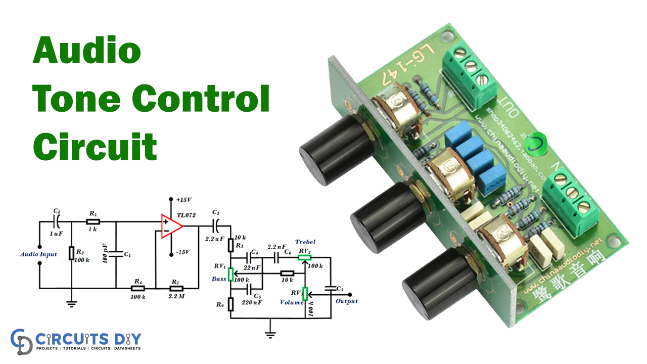
In the world of sound engineering, a simple passive tone control circuit diagram is an invaluable tool for musicians looking to create intricate, detailed soundscapes. Not only does this type of diagram allow for precise control over the frequency ranges of a sound, but it can also be used to create complex sound effects that are both pleasing to the ear and highly effective in the studio.
A simple passive tone control circuit diagram is essentially a series of interconnected transistors and resistors that are connected to a single potentiometer, or “pot.” This pot allows the sound engineer to adjust the levels of several different frequency bands in order to create a desired sound. By manipulating the incoming signal through the potentiometer, the engineer can create a wide range of different sonic effects, from subtle changes to deep drastic ones.
For those who have little experience in the use of circuitry and diagrams, a simple passive tone control circuit diagram may appear daunting. Fortunately, there are several resources available to aid novice engineers in understanding the basics of this type of diagram. The best place to start is typically with a diagram that is already created and ready to be used. This type of diagram will provide an engineer with all the information required to construct the circuit, as well as visual representations of each component and its corresponding connections.
Although the use of a passive tone control circuit diagram may seem intimidating at first, once the basics are fully understood it becomes a powerful tool for creating unique and intricate soundscapes. With the correct diagram in hand, musicians and sound engineers can now create detailed soundscapes with astonishing accuracy.

Results Page 334 About 60hz To 50hz Searching Circuits At Next Gr

3 Band Active Audio Tone Control Circuit Under Repository Circuits 45961 Next Gr

Simple Audio Loudness Control Circuit

Simple Audio Tone Control Circuit Using Tl072

Tone Control Circuit Active And Passive Engineering Projects

Basic Audio Mixer With Tone Control

Guitar Tone Circuits Octave Doctor

Boutique Amp With Baxandall Stack Page 3 The Gear

Results Page 114 About Crossover Passive 3 Way Searching Circuits At Next Gr

Amplifier Tone Stacks Monster Party Hat

Tone Control Circuit Under Audio Balance Circuits 13062 Next Gr

Simple Bass Treble Tone Control Circuit Diagram Eleccircuit Com
How To Add Passive Tone Control Preamp Talkbass Com

5 Bass Mid Treble Tone Control Circuits Projects Using Ne5532 4558 Lf353

Simple Tone Control Circuits Homemade Circuit Projects

Passive Tone Control Circuit Eleccircuit Com

Bass Bench Exploring Passive Tone Controls Premier Guitar

5 Bass Mid Treble Tone Control Circuits Projects Using Ne5532 4558 Lf353