Vibration sensor detector circuit simple metal cheap basic explanation and applications gold what is diagram how to build a make appuals com electronics ইল ক ট রন স single chip description this based on ic cs209a from the cherry semiconductors 100uh coil sense 555 circuits using arduino homemade projects deep soil ground scanner circuitry of detection results page 16 about searching at next gr bfo schematic ion electronic project maker diagrams schematics economy radar sensors detectors robotic vehicle clearance 54 off www ingeniovirtual attiny13 pi Łukasz podkalicki 3 basics 15 with code easyeda open source hardware lab longrangelocators forums category 4 storm pdf efficient design analysis pulse induction underground mines system timer circuits99

Vibration Sensor Detector Circuit

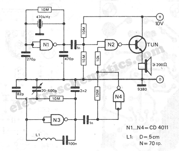
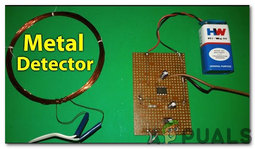
Simple Metal Detector Circuit

Cheap Metal Detector Circuit

Metal Detector Sensor Basic Explanation And Applications

Gold Detector Circuit What Is Diagram

How To Build A Metal Detector Circuit

How To Make A Metal Detector Circuit Appuals Com
Electronics ইল ক ট রন স Single Chip Metal Detector Circuit Description This Is A Simple Based On Ic Cs209a From The Cherry Semiconductors 100uh Coil To Sense

Simple Metal Detector Circuit

555 Circuits Metal Detector

Metal Detector Using Arduino

How To Make A Simple Metal Detector Circuit Homemade Projects

Deep Soil Metal Detector Circuit Ground Scanner Homemade Projects

Basic Circuitry Of Metal Detection

Results Page 16 About Gold Detector Searching Circuits At Next Gr

Basic Circuitry Of Metal Detection

Simple Bfo Metal Detector Schematic Diagram

Ion Detector Circuit Diagram Electronic Project

Metal Detector Electronics Maker

Metal Detector Circuit
Vibration sensor detector circuit simple metal cheap basic explanation and applications gold what is diagram how to build a make appuals com electronics ইল ক ট রন স single chip description this based on ic cs209a from the cherry semiconductors 100uh coil sense 555 circuits using arduino homemade projects deep soil ground scanner circuitry of detection results page 16 about searching at next gr bfo schematic ion electronic project maker diagrams schematics economy radar sensors detectors robotic vehicle clearance 54 off www ingeniovirtual attiny13 pi Łukasz podkalicki 3 basics 15 with code easyeda open source hardware lab longrangelocators forums category 4 storm pdf efficient design analysis pulse induction underground mines system timer circuits99
