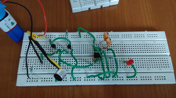
The light switch has long been an essential element of modern homes and businesses, allowing us to control the brightness of our spaces with the simple tap of a finger. But in recent years, a new technology has come on the scene—the simple clap switch circuit using 555 timers.
This circuit allows users to control the lights with a sharp clap sound instead of a flick of a switch. It works by using a timer-based circuit involving one or more 555 timers and a sound-detection device such as a microphone. When a specific sound is detected, the timer triggers a relay which cuts power to the connected lights or other devices.
In addition to its convenience, this circuit offers several advantages over traditional light switches, including increased energy efficiency and a heightened level of safety. Since users can activate the switch without having to physically reach for a switch or move around the room, it can help reduce the risk of injury from tripping or falling. The circuit also uses far less energy than a standard switch, making it an ideal choice for those looking to reduce their energy consumption.
For those interested in building their own simple clap switch circuit using a 555 timer, there are a few basic steps. First, the components must be assembled and wired correctly. This includes connecting the timer, microphone, and relay together, as well as providing power for the timer itself. Once everything is wired correctly, the sensitivity of the microphone should be adjusted to ensure the right sound threshold is met before activating the switch.
While assembling a simple clap switch circuit may require some technical knowledge, the results are worth the effort. By providing users with an automated way of controlling lights and appliances, these circuits can make any home or business smart and efficient. And with the backing of a reliable timer, users can count on their claps to do the trick every time!

Simple Clap Switch Circuit Using Transistors Tested

Clap Switch Circuit Diagram Working And Its Applications

Clap Switch Circuit Diagram Using Ic 555

Simple Clap Switch Circuit Using 555 Timer
Pcb Layout Tips For A Clap Switch Circuit Design Blog Circuitmaker

Simple On Off Switch 555 Timer Ic Tinkercad

Simple Clap Switch Circuit Using Ne555 Precision Timer Ic

Clap Switch Circuit Using Ic 555

9 Way Clap Switch Circuit Eeweb

4 Simple Clap Switch Circuits Tested Homemade Circuit Projects

Making A Simple Clap Switch Embedded Lab

4 Simple Clap Switch Circuits Tested Homemade Circuit Projects

Clap Switching International Journal Of Scientific And Engineering

Clap Switch Circuit Using 555 Timer Ic A Tutorial On How To Construct Application Of Fritzing Beta Steemit
Clap Switch Controller By Using Ic555 Timer

Clap Switch Circuit Electronic Project Using 555 Timer Projects Q A Electronics Lab Com Community

Sensitive Clap Switch Circuit