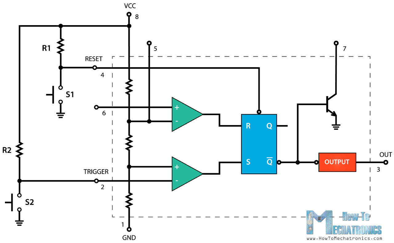
The 555 Timer is a physical device that helps us better understand how electrical circuits work. Developed in 1971, it's one of the most widely used integrated circuits ever created. It can be used to regulate the timing and flow of electricity, and it's controlled by a range of external components. Its basic operation is simple: when a specific voltage is applied to the 555 Timer pin, a circuit is completed, which triggers the timer to begin counting down a predetermined amount of time.
Circuit diagrams provide a visual representation of how components are arranged in an electrical circuit, and the Simple Circuit Diagram of the 555 Timer makes it easy for technicians and engineers alike to understand how the device works. It also provides a powerful tool for troubleshooting and debugging complex systems.
At its core, the 555 Timer is an electrical flip-flop whose output is determined by its inputs. By changing the voltage applied to the pins, the timer can be made to count down from one time interval to another. For instance, you can have it count down from one second to two seconds, allowing you to precisely control the duration of a process or event.
In addition to timing, the 555 Timer can also be used as a pulse generator. This is achieved by connecting the reset pin to the trigger pin. Every time the reset pin is triggered, the timer will start to count down from its current state.
The 555 Timer is a simple but incredibly versatile component, and its uses are limited only by your imagination. From controlling the opening and closing of doors to generating oscillations for use in musical instruments, it has been used in countless applications over the last four decades. For anyone looking to understand how electrical circuits work, the Simple Circuit Diagram of the 555 Timer is an essential tool.

555 Timer Ic Working Principle Block Diagram Circuit Schematics

Simple Tone Generator Circuit Using Ne555 Timer Ic

Adjule Single Dual Led Flasher Using 555 Timer Ic Electronic Projects Design Ideas Electronics Lab Com Community

Week 1 555 Timer

555 Timer Circuit Electronics Projects

Simple Timer Circuit Using Ic 555

Flashing Led Circuit Diagram Using 555 Timer Ic

555 Timer Tutorial And Circuits Build Electronic

Introduction To The 555 Timer Circuit Basics

The 555 Timer Based Alarm Circuit With Automatic Reset And Multiple Scientific Diagram

555 Timer Tutorial How To Configure A Ic

Simple Inverter Circuit Using Ic 555

Boost Converter Circuit Using 555 Timer Ic

Pwm Using 555 Timer Circuit And Working Ic

555 Timer Ic Pin Configuration Modes Its Applications

1 To 20 Minute Timer Circuit Using 555 Ic

555 Timer Tutorial And Circuits Build Electronic

555 Timer Ic Working Principle Block Diagram Circuit Schematics