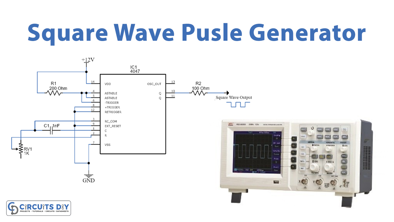
The signal generator circuit diagram is an important piece of equipment for any technophile. Whether you are a hobbyist or professional, understanding this diagram and its components can help you create and maintain a variety of electronic devices.
Signal generators come in many shapes and sizes, ranging from small pocket-sized devices to large industrial-grade machinery. They work by producing electrical signals, which can then be used to control a wide range of circuits and components. The signal generator circuit diagram shows exactly how these signals are created and manipulated, providing insight into the underlying mechanics of what's happening in the device.
At its heart, a signal generator circuit diagram is composed of two main parts: the generator itself and the transmitter. Generators use various methods to create signals, including power supplies, coils, and transistors. These signals are then modified with the transmitter, which adds, modifies, and amplifies them to achieve the desired output.
One of the most common uses of a signal generator circuit diagram is for radio frequency (RF) communications. RF technology is used in a variety of applications, such as cell phone networks and Wi-Fi networks. By studying the diagram, engineers can learn how to design and create efficient RF communications systems.
Another popular use of signal generators is for testing and debugging electronics. By understanding the different components in a circuit diagram, engineers and researchers can quickly and accurately troubleshoot any issues that arise in their projects.
Finally, signal generator circuit diagrams can be valuable tools for teaching budding engineers about electronics and engineering principles. By studying the diagrams, students can gain an understanding of how different components interact and how signals are generated and manipulated. This knowledge can then be applied to real-world problems, helping students on their journey into the field of engineering.
Signal generator circuit diagrams are essential for anyone who works with electronics or creates complex projects. With a better understanding of how these diagrams work, engineers and hobbyists alike can design and implement powerful systems with greater ease and success.

Function Generator Circuit Concepts Part 1 First Generation Generators Fgs Planet Analog

High Frequency Generator Circuit

How To Build A Sine Wave Generator Circuit With Transistor

How To Build Function Generator Circuit Diagram

Signal Generator

Square Wave Pulse Generator Circuit Using Cd4047

10 Useful Function Generator Circuits Explained Homemade Circuit Projects

4qd Tec Audio Signal Sinewave Generators

Function Generator Circuit Using Quad Opamp Ic Max494 Gadgetronicx

Schematic Diagram Showing A Signal Generator Connected To An Scientific

Pulse Generator Signal Tracer Circuit Diagrams Schematics Electronic Projects

10 Useful Function Generator Circuits Explained Homemade Circuit Projects

Clock Signal Generator Circuit Engineering Projects

What Is A Signal Generator Definition Block Diagram And Working Of Electronics Desk

Audio Frequency Generator Circuit

Function Generator Definition Working Block Diagram Circuit

Function Generator Block Diagram Phase Locking In

Design Of A Powerful Signal Generator Output Stage Analog Devices