Half wave rectifier circuit diagram theory applications full center tapped bridge explain hot 58 off www ingeniovirtual com and smoothening scientific precision analysis compare a with which has the higher output voltage quora types working its electronics reference three phase centre tap operation waveform power mosfet supply design notes circuits news dictionary of electronic engineering terms uncontrolled construction resistive load inductive d e single in an inverter mode easyeda open source hardware lab outlet 50 pcb practical androiderode capacitor filter principle electroduino discrete semiconductor textbook definition advantages disadvantages globe what is it formula electrical4u 8 two schematic diode simulation step by tutorial how to simulate using multisim analog devices edition steemit solved this chegg arduino 220v controlled simple projects conventional interfacebus 4 diagrams top ers 51 online 59 electrical academia eeweb

Half Wave Rectifier Circuit Diagram Theory Applications

Full Wave Rectifier Circuit Diagram Center Tapped Bridge
Explain Bridge Rectifier Hot 58 Off Www Ingeniovirtual Com

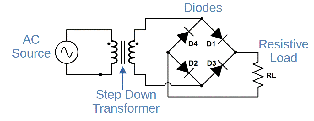
Full Wave Bridge Rectifier And Smoothening Circuit Scientific Diagram

Precision Full Wave Rectifier Circuit

Full Wave Bridge Rectifier Analysis

Compare A Bridge Rectifier Circuit With Full Wave Which Has The Higher Output Voltage Quora

Full Wave Rectifier Circuit Diagram Types Working Its Applications

Bridge Rectifier Electronics Reference

Three Phase Full Wave Rectifier

Centre Tap Full Wave Rectifier Circuit Operation Working Diagram Waveform

Bridge Rectifier Electronics Reference

Power Mosfet Bridge Rectifier Circuit Diagram

Power Supply Design Notes Rectifier Circuits Electronics News

Dictionary Of Electronic And Engineering Terms Half Wave Rectifier Circuit

Full Wave Bridge Rectifier Uncontrolled Working Construction With Resistive Load Inductive D E Notes

Single Phase Full Wave Bridge Rectifier Working In An Inverter Mode Of Scientific Diagram

Full Wave Bridge Rectifier Circuit Diagram Easyeda Open Source Hardware Lab
Half wave rectifier circuit diagram theory applications full center tapped bridge explain hot 58 off www ingeniovirtual com and smoothening scientific precision analysis compare a with which has the higher output voltage quora types working its electronics reference three phase centre tap operation waveform power mosfet supply design notes circuits news dictionary of electronic engineering terms uncontrolled construction resistive load inductive d e single in an inverter mode easyeda open source hardware lab outlet 50 pcb practical androiderode capacitor filter principle electroduino discrete semiconductor textbook definition advantages disadvantages globe what is it formula electrical4u 8 two schematic diode simulation step by tutorial how to simulate using multisim analog devices edition steemit solved this chegg arduino 220v controlled simple projects conventional interfacebus 4 diagrams top ers 51 online 59 electrical academia eeweb
