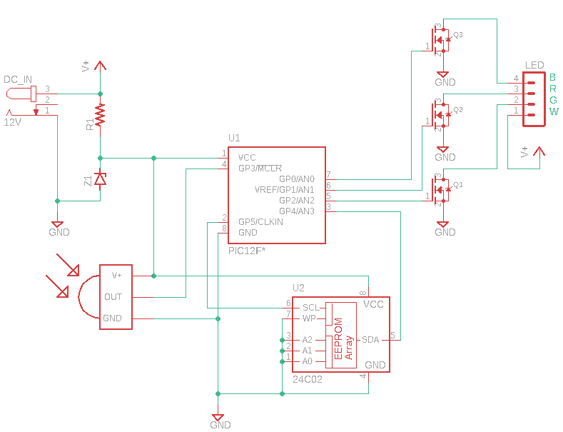
If you’re looking for a way to control your RGB LED lights, then an RGB LED Controller Circuit Diagram might be just what you need. An RGB LED Controller Circuit Diagram is a schematic representation of the components used in a circuit that allows you to adjust the brightness, color and other settings of an RGB LED light. This type of circuit diagram is used to control the effects of lighting in various applications such as automotive, decorative, and industrial lighting.
The RGB LED Controller Circuit Diagram typically consists of several components that work together to control the lighting effect. These components include a voltage regulator, a microcontroller, a driver circuit, a power supply, and resistors. The voltage regulator is used to adjust the power supply voltage to the required level. The microcontroller is used to keep track of the settings and execute the instructions set by the user. The driver circuit is used to adjust the brightness and color of the LED light. The resistors are used to control the current-limiting of the LED.
In order to make use of an RGB LED Controller Circuit Diagram, you need to have some knowledge of electrical engineering and circuit diagram construction. You need to be familiar with the components and how they interact with each other. Once you’ve learned the basics, you can create your own circuit diagram and start controlling your LED lights.
For those who don’t have the time or expertise to construct their own RGB LED Controller Circuit Diagram, there are a number of retailers that offer pre-made diagrams. These diagrams come with detailed instructions and are easy to follow. And best of all, all of the components are already included, so you don’t have to purchase them separately.
Whether you’re a novice or a professional, an RGB LED Controller Circuit Diagram can help you control the lighting effects of your LEDs. With this type of circuit diagram, you can customize the brightness and color of your LED lights with ease. If you’re looking for a way to bring life to your projects, then an RGB LED Controller Circuit Diagram is the way to go.

Arduino Based Rgb Led Strip Controller

Amplifier For Rgb Led Strips Electronics Projects Circuits
Rgb Led Controller Circuit The Working Principle And How To Make One

Rgb Led Strip Kit

Rgb Light Strip Controller Circuits Homemade Circuit Projects

Ltc3212 Typical Application Reference Design General Led Driver Arrow Com

Rgb Led Bulb Circuit Diagram Using 555 Timer Ics

Smart Rgb Led Controller Techsaw
Bluetooth To Control Rgb Led Color Eeweb

Rgb Light Strip Controller Circuits Homemade Circuit Projects

Led Tutorials Rgb Controller Installation

Rgb Led Controller Using Atmega328 Electronics Lab Com

Rgb Led Driver

Rgb Led Driver

555 Ic Based Rgb Led Driver Eeweb

Multifunction Rgb Led Controller Using Pic12f675

Controlling Rgb Led Colour Using Atmega16 Part 19 46

ترجمة سجق النصرانية 555 Rgb Led Controller Love2tour Com

Circuit Diagram Of The Proposed Led Driver For Rgb Strings Scientific