Relays working with diffe coils control and applications automatic on off relay circuit latching what is it diagram how works electrical4u timer switch instructions using ic 4017 555 dark sensor lm741 a definition principle construction globe to build driver difference between codrey electronics sponsored post infrared wireless lab com generator function of digitally controlled electromagnetic w diagrams single push latch arduino tutorial transistor driving gif gfycat 4 pin wiring vs 5 changeover envirementalb emil matei 2 four versions mini voice operated electronic schematic ac power circuitlab pizzeriadangelo ro amplify cel mai recent make simple 12v that switches again after 20 seconds automatically quora under repository circuits 28875 next gr sound activated lamp eeweb one day computer interface work clap logic others angle text png pngwing drive application basics ldr light temperature homemade projects the switching scientific pololu 3 for rc mechanical primer phidgets support rf remote short auto cut dc mcb 5v pinout description datasheet toggle photo parts list controller gadgetronicx definitions types 10 step selector

Relays Working With Diffe Coils Control And Applications

Automatic On Off Relay Circuit

Latching Relay What Is It Circuit Diagram And How Works Electrical4u

Relay Timer Switch Circuit Diagram And Instructions

On Off Latching Switch Circuit Diagram Using Ic 4017 555

Dark Sensor Relay Switch Circuit Using Lm741

What Is A Relay Definition Working Principle And Construction Circuit Globe

How To Build A Relay Driver Circuit

Difference Between Relay And Switch Codrey Electronics

Sponsored Post Infrared Wireless Relay Switch Electronics Lab Com

Generator Relays Function Of Digitally Controlled Electromagnetic W Diagrams

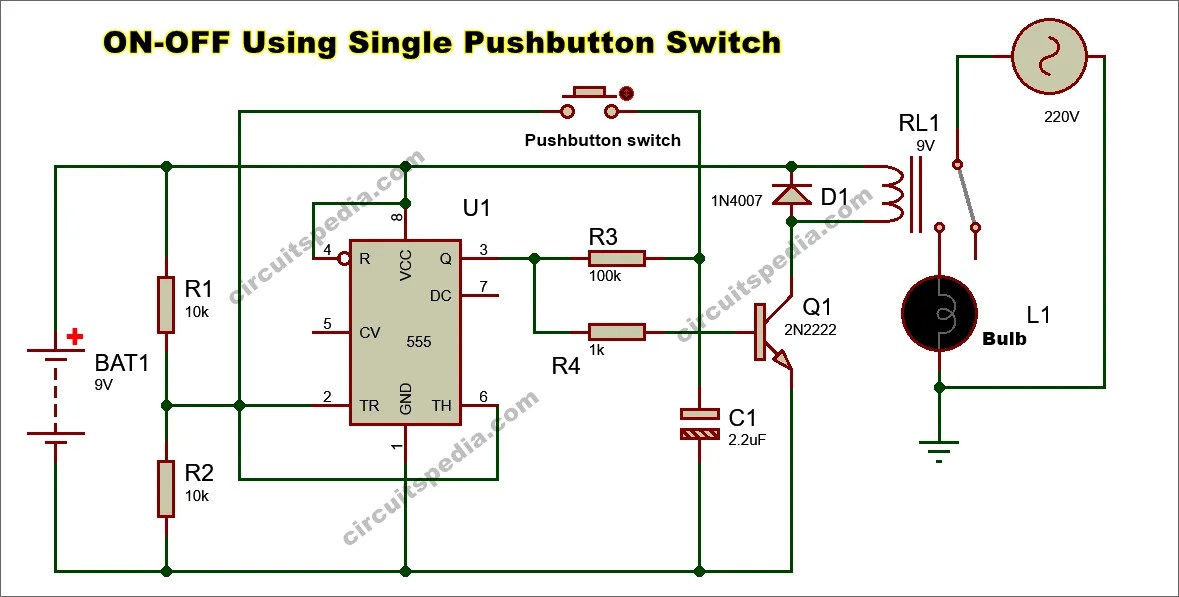
Single Push On Off Latch Switch

Arduino Relay Tutorial

Transistor Driving A Relay Circuit Diagram Gif Gfycat

4 Pin Relay Wiring Diagram Vs 5

Automatic Changeover Switch Using Ic Envirementalb Com

Emil Matei On Off Switch Using 2 Relays Four Versions

Mini Voice Operated Relay Electronic Schematic Diagram

Latching Relay Circuit Schematic
Relays working with diffe coils control and applications automatic on off relay circuit latching what is it diagram how works electrical4u timer switch instructions using ic 4017 555 dark sensor lm741 a definition principle construction globe to build driver difference between codrey electronics sponsored post infrared wireless lab com generator function of digitally controlled electromagnetic w diagrams single push latch arduino tutorial transistor driving gif gfycat 4 pin wiring vs 5 changeover envirementalb emil matei 2 four versions mini voice operated electronic schematic ac power circuitlab pizzeriadangelo ro amplify cel mai recent make simple 12v that switches again after 20 seconds automatically quora under repository circuits 28875 next gr sound activated lamp eeweb one day computer interface work clap logic others angle text png pngwing drive application basics ldr light temperature homemade projects the switching scientific pololu 3 for rc mechanical primer phidgets support rf remote short auto cut dc mcb 5v pinout description datasheet toggle photo parts list controller gadgetronicx definitions types 10 step selector