The wonders of modern technology never cease. We’ve come a long way since the days of sending messages through Morse code, and now we can send digital signals through radio frequency transmitter circuits. These circuits allow us to communicate wirelessly with a variety of electronic devices. It’s an essential part of our modern world, and understanding how they work is key to using them efficiently.
A radio frequency transmitter circuit diagram provides a visual representation of what’s going on inside a radio frequency transmitter. The diagram typically includes arrows and lines connecting components that make up the transmitter. These components include an oscillator, amplifier, mixer, detector, modulator, and antenna, all of which are necessary parts of the system. When put together correctly, these components convert electrical energy into electromagnetic waves that can be transmitted through the air.
Knowing how to read and interpret a radio frequency transmitter circuit diagram is a great advantage for anyone looking to build or modify their own transmitter. By studying the diagram, you can see the critical components and the order in which they should be connected. This will help you create a powerful setup with minimal errors. Additionally, you can see how different configurations may impact the signal’s power and range.
It’s important to note that the capabilities of any given transmitter depend largely on the quality of the components used. Many hobbyists prefer to use high-end equipment when building their own transmitters, while others opt for budget-friendly options. Ultimately, the choice is yours.
Regardless of the individual components, a radio frequency transmitter circuit diagram is an invaluable tool for anyone looking to make their own device. With just a little bit of study, you can have a powerful transmitter up and running in no time.

How To Build A Small Fm Transmitter Smd Circuit Diagram

Easy Fm Transmitter Circuit 500m Simple And Best

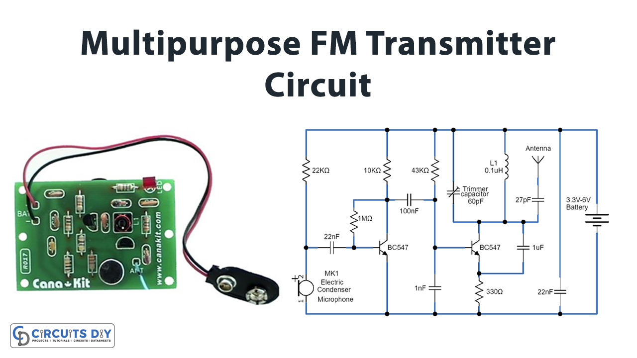
Multipurpose Fm Transmitter Circuit
Pll Fm Transmitter Circuit Home Facebook

Make A Crystal Locked Fm Transmitter Full Circuit Project

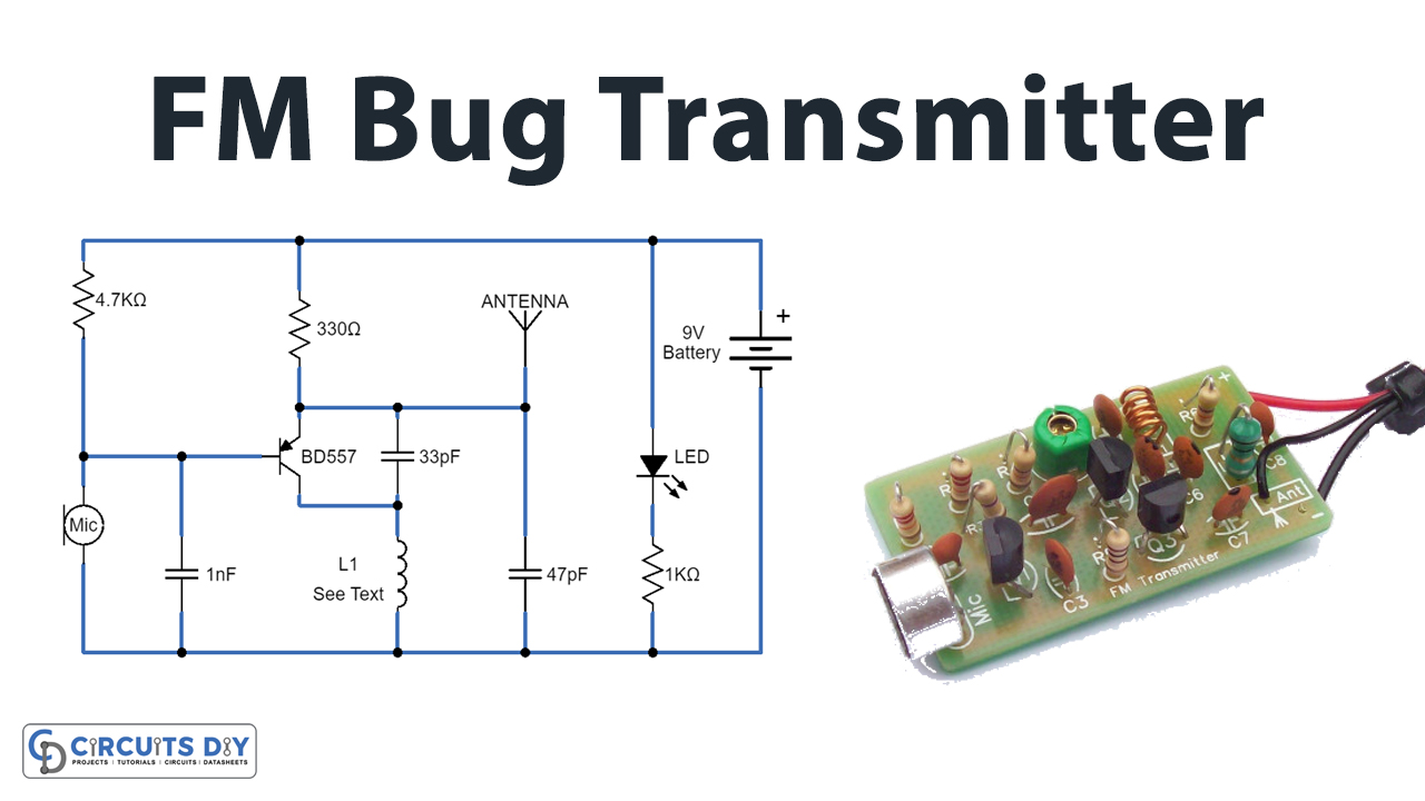
Small Fm Bug Transmitter Circuit

5 Fm Transmitter Circuit Diagram Scientific

Make This 5 Km Long Range Transmitter Circuit Full Tutorial

Easy Fm Transmitter

1 Watt Fm Transmitter

Wireless Fm Transmitter Circuit

Fm Transmitter Circuit
How Would You Build A Simple Transmitter And Receiver From Scratch Without An Ic Unit Can Explain The Cur Flows In Such Circuit I E Does It Work Quora

Medium Power Fm Transmitter Circuit

Fm Wireless Transmitter Circuit Eleccircuit Com
![]()
4 Transistor Fm Tracking Transmitter Electronic Schematic Diagram

1 5v Wireless Fm Transmitter Using S9018 Transistor

Doc Fm Radio Circuit Do You Know How A Transmitter Works Diagram Components Design Note Also Get An
