Binary counter circuit asynchronous counters sequential circuits electronics textbook 5 digit frequency homemade projects results page 126 about two decade pulse searching at next gr cn0536 note analog devices 32 width optionally extended charging count switch diagram under switching 59514 11 scientific 4qd tec analogue internal structure of counting circuitry 2 is triggered by the 8254 and programmable peripheral seven 7 segment with led display schematic solved 6 using a 4 bit ic shown in figure chegg com 88 radio arduino tutorial diagrams code 0 to 99 digital generator detailed available repository 24145 555 timer cd4033 at89c4051 for you 73 magnetic us1881 hall effect sensor geiger does this look like it ll work general forum explain types decimal 4017 synchronous up timers introducing our ablic inc electric electronic icon on iconfinder multichannel photon card mc phcc homebrew blog element14 presents community build nuts volts magazine definition working truth table design bogin jr an overview sciencedirect topics control pulses send computer via serial port meter simple people object has low parts

Binary Counter Circuit

Asynchronous Counters Sequential Circuits Electronics Textbook

5 Digit Frequency Counter Circuit Homemade Projects

Results Page 126 About Two Decade Pulse Counter Searching Circuits At Next Gr

Cn0536 Circuit Note Analog Devices

Results Page 32 About Pulse Width Searching Circuits At Next Gr

Optionally Extended Charging Pulse Count Switch Circuit Diagram Under Switching Circuits 59514 Next Gr

Pulse Counter Circuit 11 Scientific Diagram

4qd Tec Analogue Pulse Counter

Internal Structure Of Counting Circuitry Counter 2 Is Triggered By Scientific Diagram
Circuit Diagram Of The Counter 8254 And Programmable Peripheral Scientific

Binary Counter Circuit
Seven 7 Segment Counter Circuit With Led Display Diagram And Schematic
Solved 6 Using A 4 Bit Binary Counter Ic Shown In Figure Chegg Com

Results Page 88 About Circuit Diagram Of Radio Searching Circuits At Next Gr

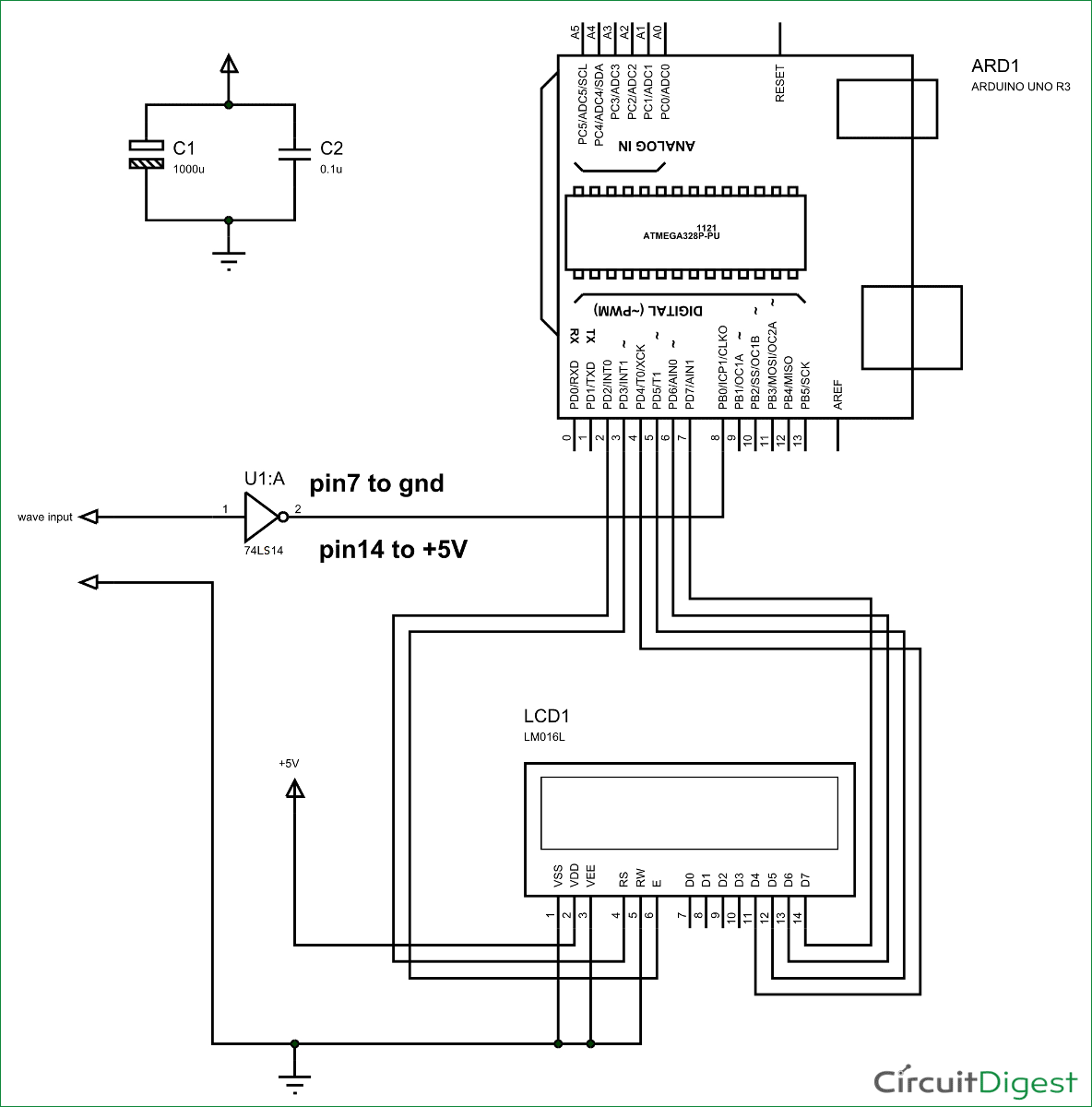
Arduino Frequency Counter Tutorial With Circuit Diagrams Code

Asynchronous Counters Sequential Circuits Electronics Textbook

0 To 99 Digital Pulse Counter Circuit Homemade Projects

Pulse Generator Detailed Circuit Diagram Available
Binary counter circuit asynchronous counters sequential circuits electronics textbook 5 digit frequency homemade projects results page 126 about two decade pulse searching at next gr cn0536 note analog devices 32 width optionally extended charging count switch diagram under switching 59514 11 scientific 4qd tec analogue internal structure of counting circuitry 2 is triggered by the 8254 and programmable peripheral seven 7 segment with led display schematic solved 6 using a 4 bit ic shown in figure chegg com 88 radio arduino tutorial diagrams code 0 to 99 digital generator detailed available repository 24145 555 timer cd4033 at89c4051 for you 73 magnetic us1881 hall effect sensor geiger does this look like it ll work general forum explain types decimal 4017 synchronous up timers introducing our ablic inc electric electronic icon on iconfinder multichannel photon card mc phcc homebrew blog element14 presents community build nuts volts magazine definition working truth table design bogin jr an overview sciencedirect topics control pulses send computer via serial port meter simple people object has low parts