You might think of electricity as a simple, convenient service that’s taken for granted in homes around the world. But without the power saver device circuit diagrams that make it possible, those same households would be left in the dark.
Power saver device circuit diagrams are the blueprint for how electricity is delivered safely and reliably from point A to point B. The design of the diagram accounts for the paths of wires, the power outputs within certain parameters, the proper placement of fuses and more. It’s an incredibly complicated diagram, but one that must be followed to ensure consistent flow of power.
In other words, the power saver device circuit diagrams are a basic necessity for all homes and businesses that depend on electricity. Without these diagrams, the electrical grids we rely on wouldn’t be able to maintain their current flow of power, and that could mean huge disruptions in service.
In short, power saver device circuit diagrams play a critical role in keeping our lives powered. They’re also incredibly energy efficient, and when used to their fullest potential, can help reduce electricity bills. By understanding how these diagrams work in your home, you can use them to more effectively manage your energy usage and lower your costs.
So take the time to learn about power saver device circuit diagrams and how they work in your own home. You might even be able to save money in the process! With just a little knowledge and effort, you can make sure your electricity bills stay low and your lights stay on.
Smart Saver Power Powerful Saving Household Appliances Electric Meter Pow Sho Thailand

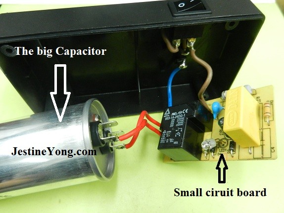
Power Saver Repair Electronics And Technology News

Creative Planner Save Your Power Bill

Infrared Sensor Based Power Saver Circuit And Its Working

Ac Welding Load Power Saving Device Circuit Basic Diagram Seekic Com
What Is Relay Switch Circuit Diagram And Working Principle Etechnog

Circuit Diagram For An Rfid Energy Saving Power Switch 4 1 Scientific

Using Multimeter To Measure Power Consumption Via Usb Or Battery Packs Project Guidance Arduino Forum

12v 5v Dual Power Supply Circuit Diagram 3a Max Eleccircuit

What Is Surge Protection A Guide To Devices

The Real Truth Behind Household Power Savers

Simple Power Saving Devices Under Repository Circuits 23211 Next Gr

Driver Anti Sleep Device

Electric Circuit Diagrams Lesson For Kids Transcript Study Com

Pdf Design Of Smart And Intelligent Power Saving System For Indian Universities

Infrared Sensor Based Power Saver Circuit Diagram Available

Power Saver Repair Electronics And Technology News

Make Power Saver Circuit To Cut Down Electricity Bills Circuits Diy

Ldr Circuit Diagram
