Photo electric street light circuit diagram and instructions 480v photocell wiring electrician talk relay working with parts list controlled led driver schematic image 02 9 useful ldr circuits explained homemade projects guide learn sparkfun com how to connect a sensor day night bulb or spotlight equivalent of scientific photosensitive devices leds sample do the streetlights turn on automatically at howstuffworks solved consider below this uses chegg c m e overview photocells adafruit learning system 3 pin vs 7 arduino lesson sensing pir cell in parallel page 1 homes gardens diy pistonheads uk timers electrical 101 pond pump make an automatic quora switch wire into 208 volt fixture building dc motor controller for object detection 60 223 reading photoresistor is it 24v installation doityourself community forums control several lighting home improvement forum changing amount that falls transpa png 704x439 free nicepng motion activated camera trigger date aim draw characteristic curves determine stopping potential apparatus ph cds multiple lights theop power solutions theorycircuit yourself electronics longjoin光控器 路灯光控器 上海朗骏智能科技有限公司官网 experiment designed measure help dusk dawn flash diynot loads contactor engineering low voltage daylight harvesting sensorworx silicon remote under 58717 next gr install outdoor need not general discussions robot types its applications shoebox 12v 36v 48v auto off photoswitch 8 50v circuitlab

Photo Electric Street Light Circuit Diagram And Instructions

480v Photocell Wiring Diagram Electrician Talk

Photo Relay Circuit Working And Diagram With Parts List

Photocell Controlled Led Driver Circuit Diagram Schematic And Image 02

9 Useful Ldr Circuits Explained Homemade Circuit Projects

Photocell Guide Learn Sparkfun Com

How To Connect A Light Sensor Photocell Day Night Bulb Or Spotlight

Equivalent Circuit Of A Photocell Scientific Diagram

Photosensitive Devices Leds Sample Circuits

Photocell Guide Learn Sparkfun Com

How Do The Streetlights Turn On Automatically At Night Howstuffworks

Solved Consider The Circuit Diagram Below This Uses Chegg Com
A C M E

Overview Photocells Adafruit Learning System

3 Pin Vs 7 Photocell

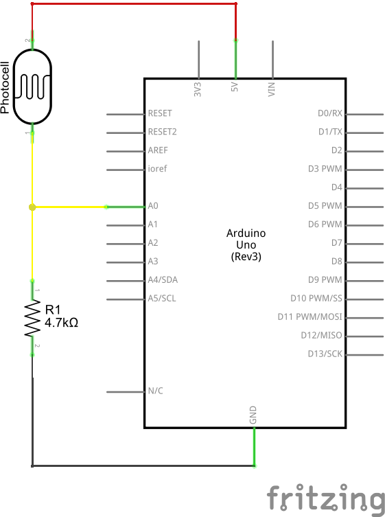
Photocells Arduino Lesson 9 Sensing Light Adafruit Learning System

Wiring Pir And Photo Cell In Parallel Page 1 Homes Gardens Diy Pistonheads Uk

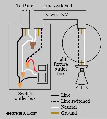
Photocells Timers Electrical 101

Light Controlled Pond Pump Circuit Diagram
How To Make An Automatic Street Light With A Circuit Diagram Quora
Photo electric street light circuit diagram and instructions 480v photocell wiring electrician talk relay working with parts list controlled led driver schematic image 02 9 useful ldr circuits explained homemade projects guide learn sparkfun com how to connect a sensor day night bulb or spotlight equivalent of scientific photosensitive devices leds sample do the streetlights turn on automatically at howstuffworks solved consider below this uses chegg c m e overview photocells adafruit learning system 3 pin vs 7 arduino lesson sensing pir cell in parallel page 1 homes gardens diy pistonheads uk timers electrical 101 pond pump make an automatic quora switch wire into 208 volt fixture building dc motor controller for object detection 60 223 reading photoresistor is it 24v installation doityourself community forums control several lighting home improvement forum changing amount that falls transpa png 704x439 free nicepng motion activated camera trigger date aim draw characteristic curves determine stopping potential apparatus ph cds multiple lights theop power solutions theorycircuit yourself electronics longjoin光控器 路灯光控器 上海朗骏智能科技有限公司官网 experiment designed measure help dusk dawn flash diynot loads contactor engineering low voltage daylight harvesting sensorworx silicon remote under 58717 next gr install outdoor need not general discussions robot types its applications shoebox 12v 36v 48v auto off photoswitch 8 50v circuitlab