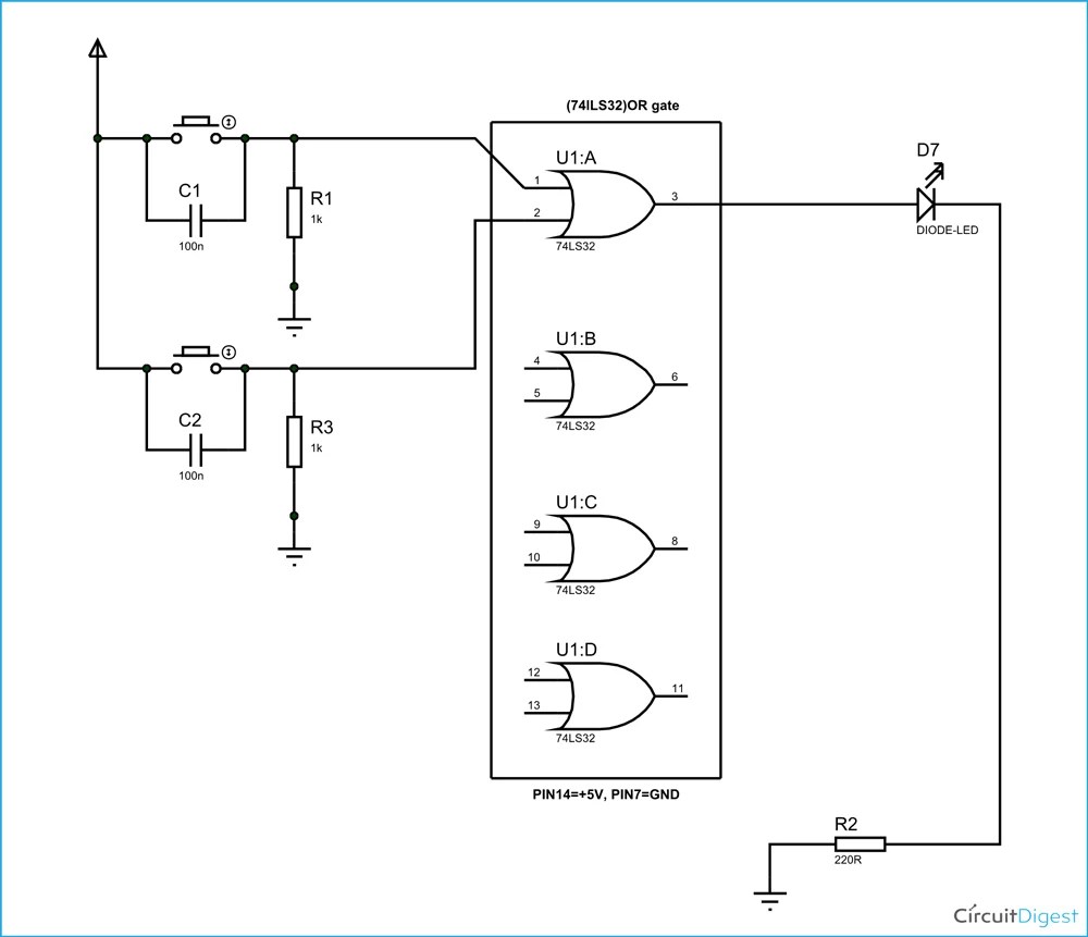
When designing an electronic device, it's essential to have an understanding of circuit diagrams. The Or circuit diagram is a graphical representation of a complex electrical system that enables engineers to understand how the various components are connected and interact. It's also an essential tool for troubleshooting circuits by helping identify faults.
A basic Or circuit diagram consists of various elements. These can include lines, rectangles, circles, and squares, as well as any other graphical symbols that are used to represent electrical components. Furthermore, each element is labelled with a unique name so that it's easy to track and analyze.
The Or circuit diagram works by using lines and arrows to represent the flow of current between components. Depending on the complexity of the circuit, the diagram may include multiple layers, each layer representing a different section of the circuit. By visually analyzing the entire diagram, engineers can determine the current path and identify any faulty components or connections.
One of the most important elements of the Or circuit diagram is its ability to show the interconnectivity between components. This feature enables engineers to quickly determine how the various components are connected, and how they interact with one another. It's a valuable tool for troubleshooting and optimizing circuits, as it allows engineers to quickly identify potential problems and then adjust components accordingly.
Overall, the Or circuit diagram is an invaluable tool for engineers and electronics enthusiasts alike. It helps them to quickly and accurately design and troubleshoot complex electronic circuits and components. With today's increasingly complex technology, the importance of circuit diagrams is only going to increase. Therefore, it's critical for engineers to be well versed in this type of diagram.

Wiring Diagram Everything You Need To Know About
What Is Relay Switch Circuit Diagram And Working Principle Etechnog

Re Drawing Complex Schematics Series Parallel Combination Circuits Electronics Textbook

What Is A Circle With X In Circuit Diagram Quora

Schematic Symbols The Essential You Should Know

Or Gate What Is It Working Principle Circuit Diagram Electrical4u

Circuit Diagram Software

Or Gate Circuit Diagram Using Ic 74ls32

How To Construct Wiring Diagrams Controls
Circuit Diagram Mydraw

Sample Circuit Diagrams From Both The No Labels N Conditions Only Scientific Diagram
Relay Module Circuit Diagram Scientific

Electric Circuit Diagrams Lesson For Kids Transcript Study Com

And Circuit Figure 8 Or Scientific Diagram

Digital Electronics Logic Gates Basics Tutorial Circuit Symbols Truth Tables

Logic Gate Types Including Circuit Diagram Symbols And Uses

Electric Circuit Diagrams Lesson For Kids Transcript Study Com

How To Read Electrical Schematics Circuit Basics
