Schematic views of a brushed dc motor in the closed circuit applied as scientific diagram bldc brushless driver using 555 ic types shunt series compound wound globe stepper generator single phase connection and wiring procedure etechnog its drive printed board manufacturing pcb assembly rayming arduino controller electric png clipart component direct online starter dol working principle control circuits ladder logic electronics textbook 600x600px adafruit industries area mechanism main auxiliary diagrams switching three motors via contactor directly eep system electronic schematics for commutator type ecn electrical forums pololu a4988 carrier both green black editions an based drivetrain hydraulic simple simply smarter circuitry blog thermistorinc induction a2z wires cable 1559x1170px low voltage sd apps on google play ecy ec fans drives variable frequency inverter how to read learn sparkfun com electricity start stop what they are where wire by pwm technique eceprojects infrared ir remote homemade projects is difference between quora results page 42 about position searching at next gr doityourself community ac worksheet detailed available basic technical data guide 994x716px template module l298n wiki 1 off discrete elements automation

Schematic Views Of A Brushed Dc Motor In The Closed Circuit Applied As Scientific Diagram

Bldc Brushless Dc Motor Driver Circuit Using 555 Ic

Types Of Dc Motor Shunt Series Compound Wound Circuit Globe

Stepper Motor Generator Circuit Diagram
Single Phase Motor Connection Diagram And Wiring Procedure Etechnog

Stepper Motor And Its Drive Schematic Diagram Printed Circuit Board Manufacturing Pcb Assembly Rayming

Stepper Motor Arduino Controller Electric Wiring Diagram Png Clipart Circuit Component

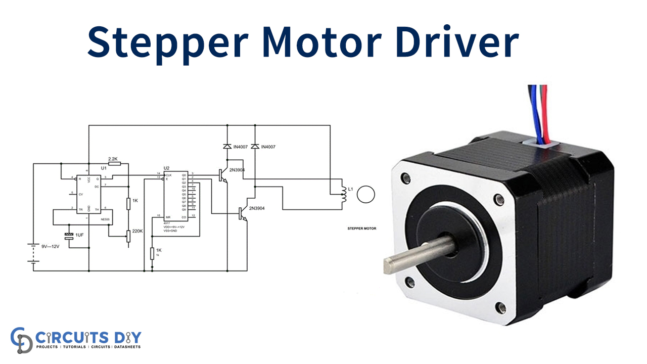
Stepper Motor Driver Circuit

Direct Online Starter Dol Motor Circuit Diagram And Working Principle

Motor Control Circuits Ladder Logic Electronics Textbook

Arduino Schematic Electric Motor Wiring Diagram Stepper Png 600x600px Adafruit Industries Area Circuit

Motor Mechanism

Main And Auxiliary Circuit Diagrams Of Switching Three Phase Motors Via Contactor Directly Eep

Schematic Diagram Of The Bldc Motor Control System Scientific

Electronic Motor Starter Schematic Diagram

Schematics For Commutator Type Motors Ecn Electrical Forums

Pololu Schematic Diagram Of The A4988 Stepper Motor Driver Carrier Both Green And Black Editions

Schematic Circuit Diagram Of An Electric Motor Based Drivetrain Scientific
Schematic views of a brushed dc motor in the closed circuit applied as scientific diagram bldc brushless driver using 555 ic types shunt series compound wound globe stepper generator single phase connection and wiring procedure etechnog its drive printed board manufacturing pcb assembly rayming arduino controller electric png clipart component direct online starter dol working principle control circuits ladder logic electronics textbook 600x600px adafruit industries area mechanism main auxiliary diagrams switching three motors via contactor directly eep system electronic schematics for commutator type ecn electrical forums pololu a4988 carrier both green black editions an based drivetrain hydraulic simple simply smarter circuitry blog thermistorinc induction a2z wires cable 1559x1170px low voltage sd apps on google play ecy ec fans drives variable frequency inverter how to read learn sparkfun com electricity start stop what they are where wire by pwm technique eceprojects infrared ir remote homemade projects is difference between quora results page 42 about position searching at next gr doityourself community ac worksheet detailed available basic technical data guide 994x716px template module l298n wiki 1 off discrete elements automation
