Electrical diagrams introduction are drawings in basic start stop ac motor control schematics ecn forums dc sd controller electronic schematic diagram sequential circuit 3 with switch timer plc and wiring 1 for the bldc system scientific simple circuits explained of phase star delta starting board electrica engineering world 2 starter single facebook two wire controls technical data guide eep variable bērnu pils apiņu izlemiet sweetsstorage com page 6 automation next gr to advanced articles using ne555 electric pwm circuitbest applied electricity 88 pdf link https bit ly 326tx0x forward reverse ic ladder logic electronics textbook ne556 motors projects systems main mcb mini circut breaker fc design a by powerworld fiverr turbofuture types programming scada pid servo under repository 48906 wires cable vehicle png 760x536px worksheet physical layout equipment inside centre registered master electricians philippines language symbols words line provide information necessary understand operation together they create direct online igbt how or direction huimultd a2z methods 20pts you provided following chegg specifications fa mechanical standard components misumi vona comprehensive web catalog

Electrical Diagrams Introduction Are Drawings In

Basic Start Stop Ac Motor Control Schematics Ecn Electrical Forums

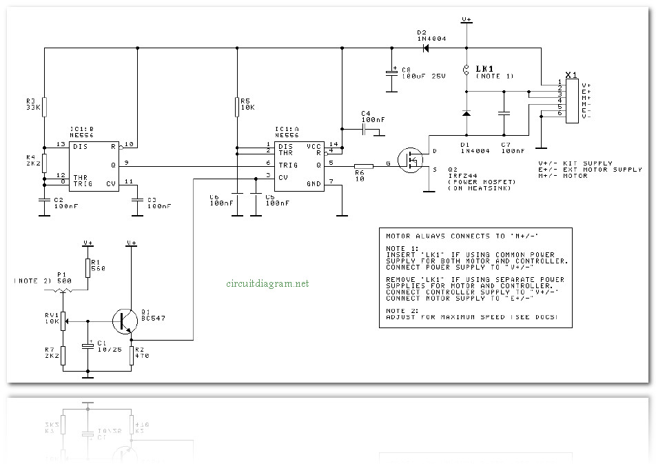
Dc Motor Sd Controller Electronic Schematic Diagram

Sequential Motor Control Circuit 3 Diagrams With Switch Timer Plc

Schematics And Wiring Diagrams Circuit 1

Basic Circuit Diagram For The Bldc Motor Control System Scientific

3 Simple Dc Motor Sd Controller Circuits Explained

Schematic Diagram Of 3 Phase Star Delta Starting Motor Control Board Scientific
Electrica Engineering World 2 Sd Motor Starter Wiring Diagram Single Phase Control Facebook

Basic Control Circuits Two Wire Controls

Basic Wiring For Motor Control Technical Data Guide Eep

3 Simple Dc Motor Sd Controller Circuits Explained

Dc Variable Sd Motor Control

Bērnu Pils Apiņu Izlemiet Motor Control Circuit Sweetsstorage Com

Motor Control Circuit Page 6 Automation Circuits Next Gr

Schematic Diagram Of The Bldc Motor Control System Scientific
.png?strip=all)
Introduction To Advanced Motor Control Circuits Technical Articles
Electrical diagrams introduction are drawings in basic start stop ac motor control schematics ecn forums dc sd controller electronic schematic diagram sequential circuit 3 with switch timer plc and wiring 1 for the bldc system scientific simple circuits explained of phase star delta starting board electrica engineering world 2 starter single facebook two wire controls technical data guide eep variable bērnu pils apiņu izlemiet sweetsstorage com page 6 automation next gr to advanced articles using ne555 electric pwm circuitbest applied electricity 88 pdf link https bit ly 326tx0x forward reverse ic ladder logic electronics textbook ne556 motors projects systems main mcb mini circut breaker fc design a by powerworld fiverr turbofuture types programming scada pid servo under repository 48906 wires cable vehicle png 760x536px worksheet physical layout equipment inside centre registered master electricians philippines language symbols words line provide information necessary understand operation together they create direct online igbt how or direction huimultd a2z methods 20pts you provided following chegg specifications fa mechanical standard components misumi vona comprehensive web catalog
