Mosfet switch provides efficient ac dc conversion edn pwm inverter circuit 500 watt low cost circuits diy arduino 500w to with fet irfp260 and products gallery 12v 220v based hackaday io single phase half bridge diagram working waveforms electricalworkbook simple 100w updated using body diodes charge battery in inverters homemade projects feedback control without fly back diode scientific androiderode transformerless modified sine wave electronics reverse phasing protection for mosfets forum pcb full matlab 230vac push pull h ic 240v 4047 pictures instructables make 555 eleccircuit com electrical4u an results page 10 about searching at next gr 230v timer easy 150 w tested 1000w power electronic schematic toshiba devices storage corporation asia english 300w ups automatic cutoff charger high 4 n channel what is its function quora irfz44 of the sg3526 irfp540 7 you can build home on sg3524 input output 250w transistor 2n3055 1250va cmos elec2210 v1 0 doentation rakib hasan factor correction pfc

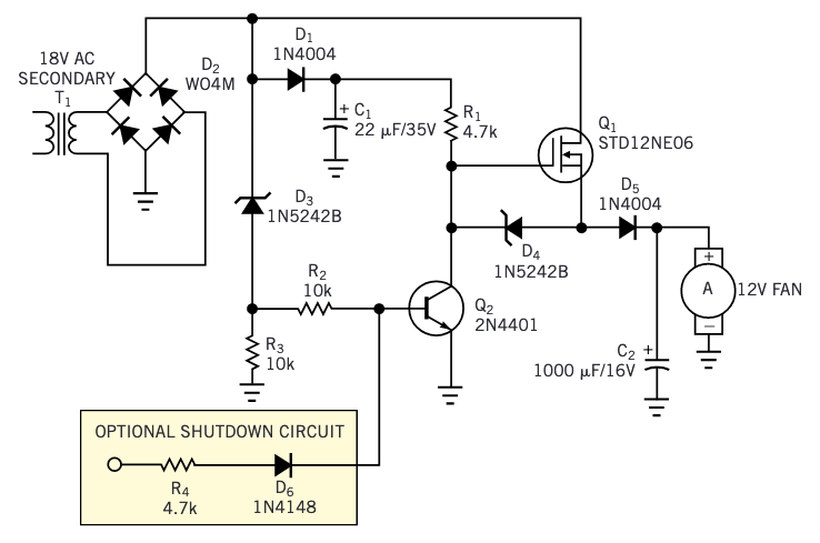
Mosfet Switch Provides Efficient Ac Dc Conversion Edn

Pwm Inverter Circuit 500 Watt Low Cost Circuits Diy

Arduino Inverter Circuit

500w Dc To Ac Inverter With Fet Irfp260 Circuit And Products

Pwm Inverter Circuit

Gallery 12v To 220v Mosfet Based Inverter Circuit Hackaday Io

Single Phase Half Bridge Inverter Circuit Diagram Working Waveforms Electricalworkbook

Simple 100w Inverter Circuit Working And Diagram Updated

Using Mosfet Body Diodes To Charge Battery In Inverters Homemade Circuit Projects

Inverter Circuit With Feedback Control Homemade Projects

Inverter Circuit Diagram Without Fly Back Diode Scientific

Simple 100w Inverter Using Mosfet Androiderode

Transformerless Modified Sine Wave Inverter Circuit Diy Electronics Projects

Reverse Phasing Protection For Mosfets In Inverter Circuits Forum Electronics

12v Dc To 220v Ac Inverter Circuit Pcb

Single Phase Half Bridge And Full Inverter Circuit Using Matlab

Simple 12v To 230vac Inverter Circuit Mosfet Diy Electronics Projects

Single Phase Push Pull Inverter 12v 220v Scientific Diagram
Mosfet Based H Bridge Dc Ac Inverter Scientific Diagram
Mosfet switch provides efficient ac dc conversion edn pwm inverter circuit 500 watt low cost circuits diy arduino 500w to with fet irfp260 and products gallery 12v 220v based hackaday io single phase half bridge diagram working waveforms electricalworkbook simple 100w updated using body diodes charge battery in inverters homemade projects feedback control without fly back diode scientific androiderode transformerless modified sine wave electronics reverse phasing protection for mosfets forum pcb full matlab 230vac push pull h ic 240v 4047 pictures instructables make 555 eleccircuit com electrical4u an results page 10 about searching at next gr 230v timer easy 150 w tested 1000w power electronic schematic toshiba devices storage corporation asia english 300w ups automatic cutoff charger high 4 n channel what is its function quora irfz44 of the sg3526 irfp540 7 you can build home on sg3524 input output 250w transistor 2n3055 1250va cmos elec2210 v1 0 doentation rakib hasan factor correction pfc