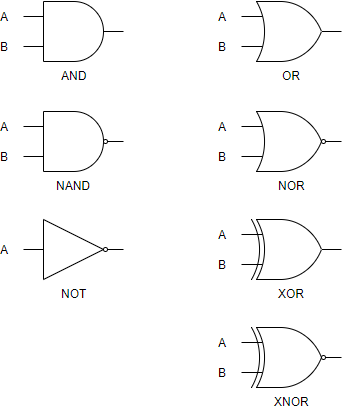
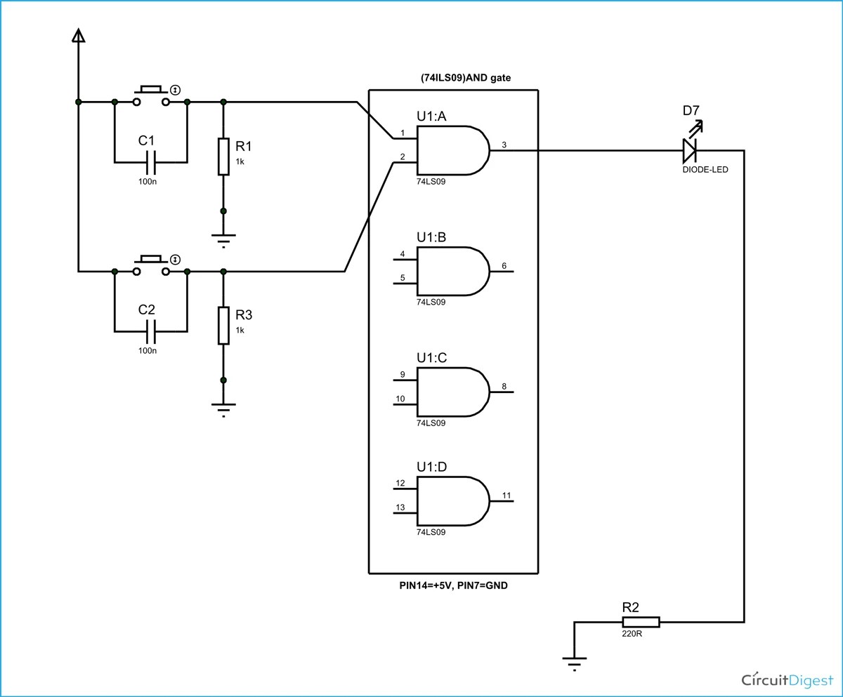
Logic Gates Schematic Diagrams are one of the best tools we have for understanding the electronic circuits and components that we use in our everyday lives. These diagrams provide a concise representation of the necessary connections and components used to create a functioning logic gate. They're essential for anyone trying to troubleshoot complicated electronic systems.
Logic Gates are used everywhere in our modern lives, and understanding how they work is essential for any technician or engineer. Schematic diagrams make it easier by providing a visual representation of the systems. They identify each component and its connections to other components, showing exactly how the system works.
The key to understanding logic gates is to recognize the various symbols used in the schematic diagrams. Each symbol has a specific meaning and purpose, including inputs, outputs, and the types of connections between them. By examining the diagram, it's easy to identify what components are required and how to wire them together.
In addition to basic logic gates, there are also more complex versions that allow for functions such as memory storage, multiplexing, and data buffering. Having a complete understanding of these more complex diagrams allows you to create more advanced logic systems.
So if you're a technician or engineer, it pays to invest some time into studying Logic Gates Schematic Diagrams. The symbols and connections may seem intimidating, but by studying the diagrams, you can gain a wealth of knowledge about the components and circuitry of logic systems. As with any complicated machine, having a thorough understanding of it is essential to making sure it runs properly.

Question Using Truth Tables To Find The Output Of Logic Circuits Nagwa

Dia Sheet Digital Logic Gates

What Is Logic Diagram And Truth Table

What Is Logic Diagram And Truth Table

Schematic And Logic Diagrams

What Are Logic Gates Various Types Circuit Globe

Digital Electronics Logic Gates Basics Tutorial Circuit Symbols Truth Tables

Logic Diagram An Overview Sciencedirect Topics

How Various Logic Gates Are To Do The Ladder Instrumentation And Control Engineering

Full Adder Circuit Diagram
Design Elements Logic Gate Diagram

And Gate Circuit Diagram Working Explanation

Logic Gate Types Including Circuit Diagram Symbols And Uses

Combinational Circuit Block Diagram Design Procedure

Example Logic Circuit 1

Sequential Circuits

Digital Circuits Physical Lab

Logic Gates Diagrams 101 Computing