Light Sensing Circuit Diagrams can help you take your projects to the next level. Whether you're a student working on a science project or an experienced electrical engineer looking for answers to complex questions, a circuit diagram is a diagramatic representation of how components are connected within an electrical system or circuit. With a light sensing circuit diagram, you can achieve the desired results in a much more efficient and accurate manner.
Light sensors are the backbone of modern electrical systems and play an important role in various applications such as security systems, automation, and control systems. A light sensing circuit diagram provides information about the electrical connections and components used to create a specific circuit. It also allows one to troubleshoot any problems that may arise.
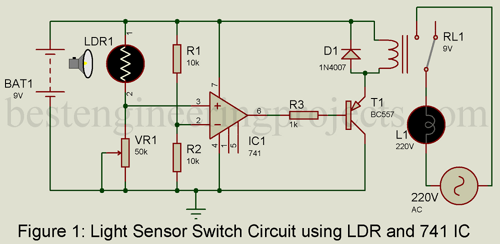
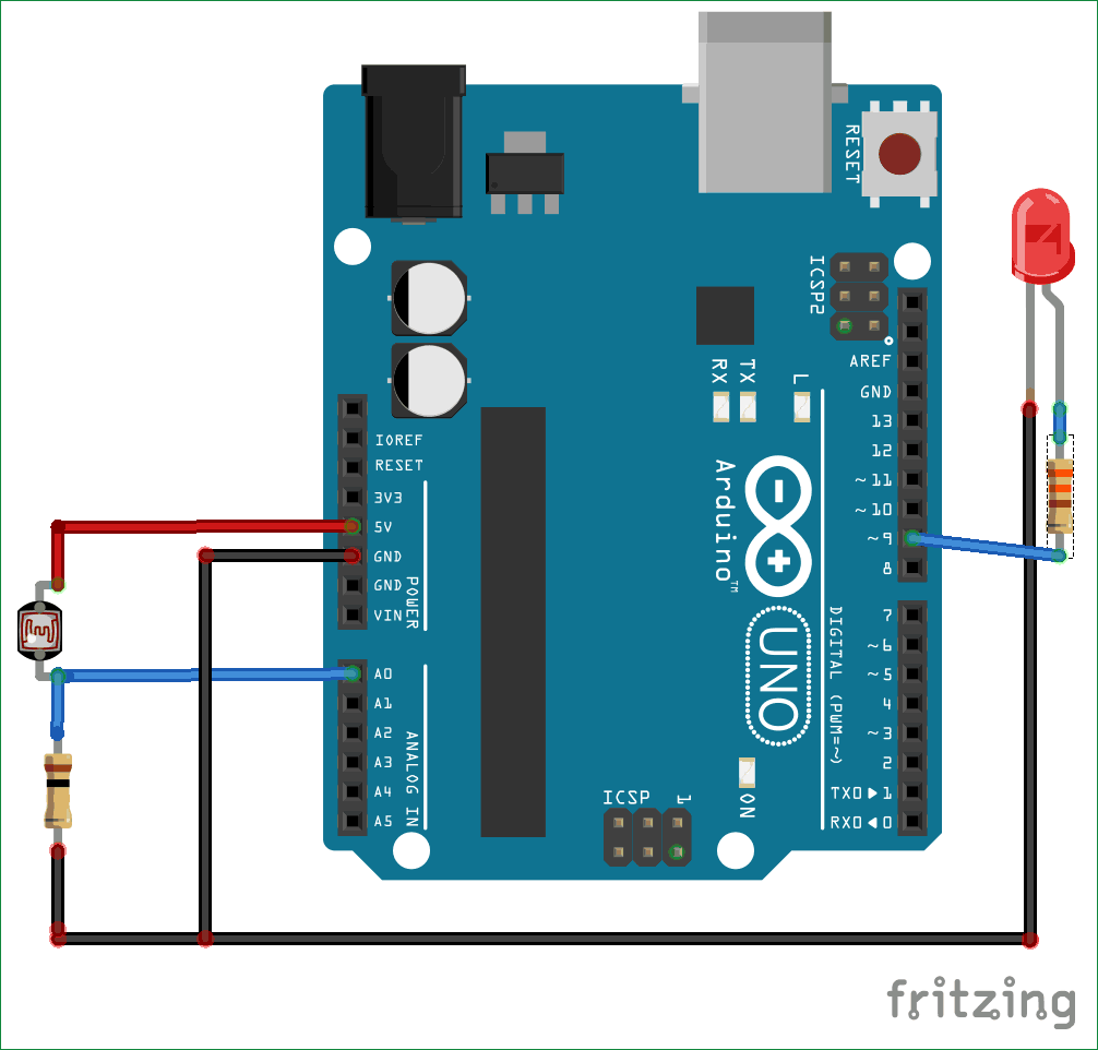
A simple light sensing circuit uses elements such as a light-dependent resistor, an LED, and a transistor. When the light changes, the resistance of the LDR changes accordingly. The changing LDR resistance sends a signal to the transistor, which then sends a current to the LED, causing it to light up. The LED is an indicator that the light has changed and can be used to modify the light sensor’s sensitivity.
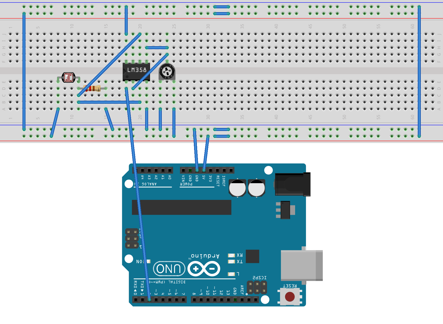
Light sensing circuit diagrams are easy to understand with a basic knowledge of electrical engineering. They provide an organized representation of the electrical connections between various components. For example, a complete circuit will show the power source, the LDR, the transistor, and the LED.
Light sensing circuit diagrams allow one to precisely develop and design advanced circuits that require multiple sensors, transistors, and other components. With a light sensing circuit diagram, it’s possible to accurately troubleshoot errors and identify the cause of any issues.
Whether you’re looking to build an advanced security system or create a new lighting system, light sensing circuit diagrams will provide the guidance you need. With their organized representation and precision, they’re sure to make your projects turn out perfectly.

Activity Led As Light Sensor Adalm2000 Analog Devices Wiki

Using Led As A Light Sensor Circuit Diagram And Instructions

Light Sensor Switch Circuit Using Ldr And 741 Ic Engineering Projects

How To Build A Simple Sensor Module By Your Own Gadgetronicx

Making Sense Of Light Sensors Edn

Using Led As A Light Sensor Eeweb

Arduino Light Sensor Circuit Using Ldr

Led As Light Sensor Electronics Do It Yourself Project

Sensor Tutorial 1 How To Design An Ldr Light Dark Using Arduino

Dark Detector Circuits Using Diffe Light Sensors

Diy Motion Sensor Light Using Led Bulb And Pir

Light Sensor Circuit Diagram Working And Its Applications

Light Dark Activated Relay

Makingalight Dark Sensor

Simple Ldr Circuit To Detect Light

Light Sensor Circuit Diagram Gadgetronicx

How To Make Automatic Daylight Sensor Switch Project Elec Circuit Com

Circuit Design Of Light Sensor And Relay Module Scientific Diagram

Light Barrier Detector Circuit Diagram