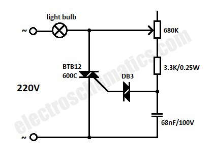
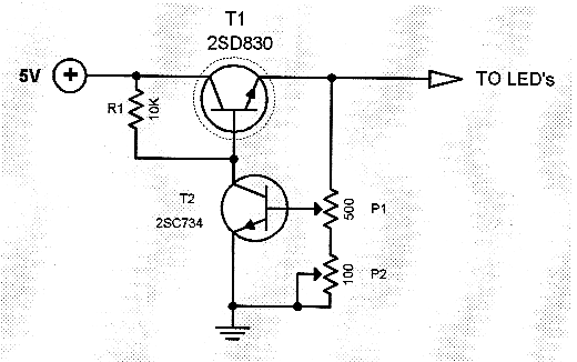
The age-old dimmer switch is something most of us take for granted in our homes. But did you know that a light dimmer schematic diagram is the backbone of these switches? That’s right - the humble dimmer switch is really just a type of electrical circuit.
What exactly is a light dimmer schematic diagram? In basic terms, it’s a drawing that shows all the components necessary for a dimmer switch to do its job. This includes everything from transformers and resistors to capacitors and transistors. You also need wires, cables, sockets, switches, and control knobs to complete the circuit.
These diagrams show the exact relationships between these components and how they interact with each other to control the brightness of lights. Knowing how to read and interpret a light dimmer schematic diagram can be extremely useful for anyone who needs to diagnose a dimmer switch issue.
That said, even if you’re not an electrical engineer, understanding some key basics about these diagrams can help you better understand the technology behind your favorite home lighting fixtures. It can also help you troubleshoot any problems you have with your switches.
Light dimmer schematic diagrams can also be used to create custom lighting effects. Knowing which components are necessary to create a given effect can help you plan your lighting design in advance. It can also save you time and money in the long run, since you won’t have to experiment with different wiring arrangements.
So, the next time you’re looking to upgrade or replace a dimmer switch, it pays to understand the underlying technology. A light dimmer schematic diagram can be your gateway to a more efficient and effective lighting setup. Plus, it’s an essential element of any home electrical maintenance guide.
%20Dimmer%20Switch%20Wiring%20Diagram.png?strip=all)
Dimmer Switch Wiring Diagram Single Pole 2 Way 3 Etechnog

Push On Led Light Dimmer Circuit With Mosfet Techsaw

Electronics Light Dimmer Forum For

Led Dimmer Circuit With Irfz44n Mosfet

400va Ac Light Dimmer Electronics Lab Com

220 V Ac Light Dimmer Circuit Diagram Fan Regulator

Microcontroller Controlled Light Dimmer

Light Dimmer Switch Circuit

Automatic Lamp Dimmer Circuit Using Triac Gadgetronicx
The Triac How Dimmer Switches Work Howstuffworks

Low Voltage Led 0 10v Dimming Usai

12v Light Dimmer Circuit

Model Theatre Lighting Dimmer Circuit Diagram

5v Led Dimmer Circuit

How To Build A Light Dimmer Circuit

Light Dimmer Circuit 1000 Watts Using Bt139 Envirementalb Com

Light Dimmer Circuit

Instrument Panel Lamp Dimmer Control Circuit Diagram And Instructions

70w Lamp Dimmer Circuit 555 Mosfet Electronics Projects Circuits