Circuit notes identifying light emitting diodes leds diode led types electronics schematic diagrams mastering arduino diagram symbol clipart best 7 segment display electric electronic icon on iconfinder symbols the essential you should know of components electrical working characteristics for or nohat free designer robots fun tri colour scientific reading and understanding various day3 seven embedded lab a programming interactivity book angle png pngegg digital circuits i how to read learn sparkfun com science rgb structure its schematics commonly labels dummies white switch basics does dual n fuse indicator work series resistor calculator engineering tools atmega32 avr component wiring wikipedia anod hd 2000x4392 3399530 pngfind kids dk find out meet l2 physical computing clip art at clker vector online royalty public domain www jebas us solved gy y figure 4 breadboard chegg area black brand photo aces jr transpa pngkey strip internal voltage information waveform lighting eleccircuit bicolor ss mini physics bipolar driver using microcontroller 555 timer ic

Circuit Notes Identifying Light Emitting Diodes Leds
Light Emitting Diode Led Types Electronics Notes

Schematic Diagrams Mastering Arduino

Led Circuit Diagram Symbol Clipart Best
![]()
7 Segment Led Circuit Diagram Display Symbol Electric Electronic Icon On Iconfinder

Schematic Symbols The Essential You Should Know

Circuit Symbols Of Electronic Components Electrical Symbol

Light Emitting Diode Led Working Circuit Symbol Characteristics

Electric Circuit Symbol For Light Emitting Diode Or Led Nohat Free Designer

Robots For Fun

Led Circuit Symbol Clipart Best

Schematic Of Tri Colour Led Scientific Diagram

Electronic Components Symbols Reading And Understanding Various

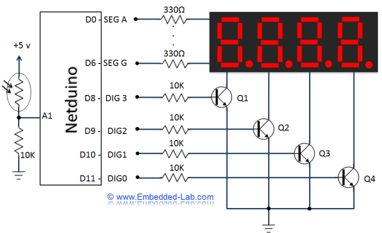
Day3 Seven Segment Led Circuit Diagram Embedded Lab

A Circuit Diagram Symbols Programming Interactivity Book

Electronic Symbol Light Emitting Diode Led Circuit Schematic Angle Electronics Png Pngegg
Light Emitting Diodes And Digital Circuits I

How To Read A Schematic Learn Sparkfun Com

Light Emitting Diode Led Working Circuit Symbol Characteristics
Circuit notes identifying light emitting diodes leds diode led types electronics schematic diagrams mastering arduino diagram symbol clipart best 7 segment display electric electronic icon on iconfinder symbols the essential you should know of components electrical working characteristics for or nohat free designer robots fun tri colour scientific reading and understanding various day3 seven embedded lab a programming interactivity book angle png pngegg digital circuits i how to read learn sparkfun com science rgb structure its schematics commonly labels dummies white switch basics does dual n fuse indicator work series resistor calculator engineering tools atmega32 avr component wiring wikipedia anod hd 2000x4392 3399530 pngfind kids dk find out meet l2 physical computing clip art at clker vector online royalty public domain www jebas us solved gy y figure 4 breadboard chegg area black brand photo aces jr transpa pngkey strip internal voltage information waveform lighting eleccircuit bicolor ss mini physics bipolar driver using microcontroller 555 timer ic
