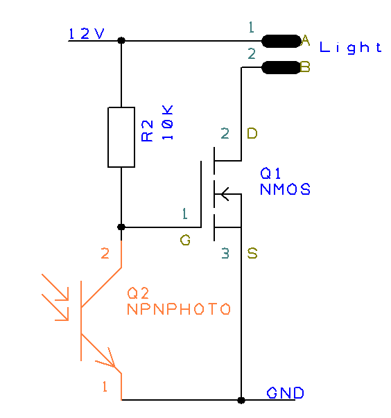
I'm sure you've seen them - those mysterious circuit diagrams used in a variety of electronics projects. Even if you don't know much about electronics, chances are you've at least heard of the Ir phototransistor circuit diagram. This powerful, yet simple, circuit is found in many uses from home automation to industrial machines. So what is an Ir phototransistor and how does it work?
An Ir phototransistor is a type of transistor that responds to light. It consists of two parts - a photodiode and a transistor connected together in a single circuit. The photodiode is used to detect incoming light, and the transistor acts as an amplifier so the output signal can be more easily analyzed. This simple combination makes the Ir phototransistor an invaluable tool for any electronics project.
The most common use for an Ir phototransistor is in remote controllers for televisions, radios, air conditioners, and other appliances. By connecting the photodiode to the transmitter (remote control), a user can control the appliance by pointing the remote at the photodiode and pressing the appropriate buttons. The photodiode then detects the light from the remote and sends a signal to the receiver, which amplifies the signal and sends it to the appliance.
Beyond its use in consumer applications, the Ir phototransistor is used in a variety of industrial and commercial applications, including machine vision systems, robotics, medical imaging, and more. In machine vision systems, the phototransistor is used to monitor movements and detect the presence of objects. In robotics, the phototransistor is used to guide a robot's movement. And in medical imaging, the phototransistor is used to detect tumors and other abnormalities.
The Ir phototransistor circuit diagram is a powerful yet simple tool that is used in a variety of applications. From controlling your television to guiding a robot, the Ir phototransistor provides a reliable and efficient way to detect light and control electrical devices. Whether you're a hobbyist or a professional, understanding the Ir phototransistor circuit diagram is an important step towards mastering the electronics field.

Light Sensitive Fire Alarm Diy Circuit Diagram With Full Explanation

Infrared Ir Receiver Schematic Pyroelectro News Projects Tutorials
Micromouse Ir Phototransistor Setup Circuitlab

Long Range Ir Transmitter

How To Build Simple Optical Switch Circuit Diagram

Improve Sensitivity Of Ir Phototransistor Receiver Sensors Arduino Forum

Wireless On Off Switch Circuit Diagram And Instructions

Phototransistor Circuit Sensors Arduino Forum

Ir Detector Circuit Using L14g2 Phototransistor

The Electronic Circuit Connecting Phototransistor And An Ir Led To Scientific Diagram

3 Connect A Phototransistor To Arduino The Robotronics
Ir And Phototransistor All About Circuits

Ir Music Transmitter And Reciever Circuit Diagram

Phototransistor Construction Circuit Diagram Its Applications

Sensitive Ir Switch Circuit

Build The Light Sensor Circuits Learn Parallax Com

Infrared Ir Sensor Using Lm324 Ic

Tape Sensor Png

Circuit Diagram Embryonic Dk