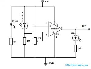
Infrared Circuit Diagrams are a key component of many electronics, but can be difficult to interpret without the right knowledge. Fortunately, with some basics about infrared sensors and a little bit of guidance on reading diagrams, anyone can learn how to design an effective infrared circuit.
An infrared circuit diagram shows the physical connections between components using lines to indicate electrical signals. This diagram is then used to figure out how each component in the circuit interacts with the other, as well as how it affects the overall output. Understanding the symbols on the diagram is key for accurately interpreting the information.
The most common infrared components you may encounter include receivers, transmitters, and controllers. Receivers detect infrared signals and translate them into electrical commands. Transmitters send out infrared signals to trigger events like switching on a light or unlocking a door. Controllers handle the input and output signals, allowing the user to control their device’s functions.
When looking at an infrared circuit diagram, first familiarize yourself with the symbols and labels. Then read theconnecting lines to determine which components interact with one another. Following this information, identify what type of connections and controls each component needs to operate properly. Finally, trace the signals and determine their flow from input to output.
To build a successful infrared circuit, you must consider the relationship between inputs and outputs, as well as the way in which each component contributes to the overall system. Infrared circuit diagrams provide detailed information about the parameters of the circuit, so with a thorough understanding of the component symbols and connections, anyone can construct an effective and efficient infrared circuit.

Infrared Ir Controlled Led Emergency Lamp Circuit Homemade Projects

Infrared Thermometer Schematics Theorycircuit Do It Yourself Electronics Projects

Ir Infrared Detector Circuit Diagram Eeweb

Ir Transmitter And Receiver Circuit Diagram

Ir Beam Breaker Circuit
![]()
Application Circuit Of Low Noise Op Amp Tc75s67tu For Pyroelectric Infrared Sensor Toshiba Electronic Devices Storage Corporation Europe Emea
Solved Design The Schematic Circuit In Maker And Chegg Com

How To Build Infra Red Remote Control Extender Circuit Diagram

Simple Infrared Transmitter Circuit

Ir Sensor Circuit Types Working Principle Its Applications

Simple Sensitive Tester For Infrared Ir Remote Control Electronic Schematic Diagram

Sensitive Ir Switch Circuit

Infrared Switch Circuit

Infrared Ir Receiver Circuit Minimizes Power Consumption Edn

Infrared Ir Sensor Using Lm324 Ic

Ir Infrared Detector Circuit Diagram

Ir Remote Control Computer Interfacing

How To Build An Infrared Detector Circuit

Circuit Diagram Of Ir 3 1 Op Amp Description The Symbol Scientific