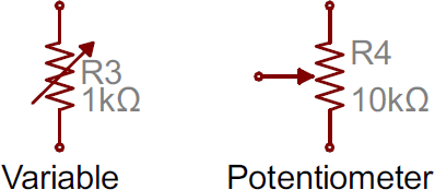
It doesn't matter if you are a hobbyist, an engineer, or just someone who loves exploring the inner workings of electronic circuits – you have to know how to read schematics. Schematics are the diagrams and blueprints that allow us to understand the complexities of an electronic circuit. But understanding them is not always easy.
The most important thing to remember when reading a schematic is to identify all the symbols and components. Symbols are the graphical representations of each component while components are physical objects such as resistors, capacitors, transistors, etc. Once you are familiar with these symbols and components, then you can start to make sense of the schematic.
Another key aspect of reading schematics is understanding how the components are connected in the circuit. This is often done with lines that represent different types of connections. If you are struggling to figure out which line is connected to what, it might be helpful to experiment with a soldering iron to see how different connections affect the circuit’s operation.
Finally, once you are familiar with the components and how they are connected, you can then start to understand how the circuit works. This is often done by drawing a diagram of the circuit with arrows to show how energy flows from point A to point B.
In short, reading schematics can be a daunting task but is essential to understanding the complexities of electronic circuits. However, with enough practice and patience, anyone can learn to read schematics and become an expert in no time. So don’t be intimidated – get out there and start learning!

How To Read A Schematic Learn Sparkfun Com

How To Read A Schematic Learn Sparkfun Com

Interpreting Electrical Schematics Petroed

How To Read The Electrical Diagram And What Are Symbols Involved In It Instrumentation Control Engineering

Electronic Diagrams Prints And Schematics Instrumentation Tools

How To Read Electrical Symbols The

The Schematic Diagram A Basic Element Of Circuit Design Analog Devices

Understanding Schematics Technical Articles

Electronic Schematics What You Need To Know

How To Read The Arduino Schematic Diagram Learn Circuitrocks

4 Ways To Read Schematics Wikihow

How To Read Electrical Schematics Circuit Basics

4 Ways To Read Schematics Wikihow

How To Read A Schematic Learn Sparkfun Com

Beginner S Guide To Reading Schematics Mcgraw Hill Education Access Engineering

Understanding Schematics Technical Articles

4 Ways To Read Schematics Wikihow
:max_bytes(150000):strip_icc()/kr7ysztofwiringdiagram-5c4df148c9e77c0001f32271.jpg?strip=all)
What Is A Schematic Diagram

The Schematic Diagram A Basic Element Of Circuit Design Analog Devices