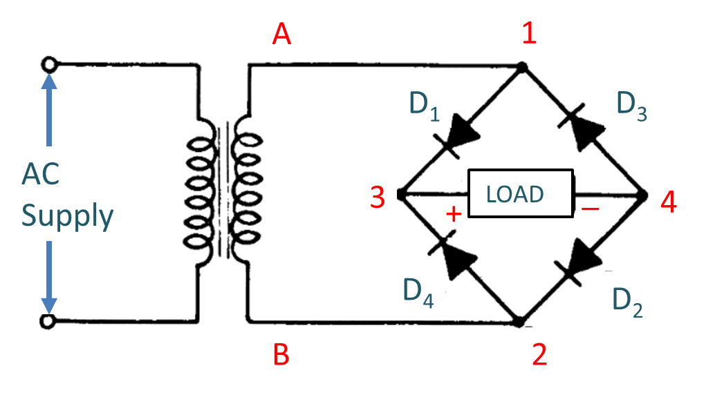
From powering your home electronics to running a business, having a stable and reliable power source is essential. One of the most efficient and cost-effective solutions is using a full wave rectifier circuit diagram. They’re simple to install and maintain, and their ability to convert alternating current (AC) into direct current (DC) saves energy while providing a steady power supply.
A full wave rectifier circuit diagram consists of two diodes that are connected in opposite directions. When an alternating current (AC) passes through the circuit, the current is converted into direct current (DC). This is done by the two diodes, which act as valves, allowing current to flow in one direction only and converting it into DC. The result is a steady, continuous flow of power with no gaps or surges.
Full wave rectifier circuits can be used for all types of applications, from powering your home electronics to providing an industrial power source. They’re popular in motor control, UPS systems, inverters, industrial automation, and many other areas. They can also be used for consumer applications such as digital displays, HVAC systems, and audio amplifiers.
The advantages of full wave rectifier circuits are numerous. They are inexpensive to build and maintain, and their efficient power output eliminates voltage peaks and reduces electrical noise. Other benefits include the flexibility to adjust the electrical parameters to suit different power requirements, as well as the ability to control speed and torque in motor control systems.
Full wave rectifier circuits provide a reliable and cost-effective solution to any power requirement. Their installation and maintenance are straightforward, and they have a high tolerance for voltage variations without compromising their performance. If you’re looking for a reliable and efficient power source, a full wave rectifier circuit diagram is the way to go.

Full Wave Rectifier Circuit Diagram Types Working Its Applications

Full Wave Rectifier Using Scr

Three Phase Full Wave Diode Rectifier Equations Circuit Diagram Electrical4u
Simulation Full Wave Rectifier Circuit With R L C Load By Multisim Scientific Diagram

Full Wave Bridge Rectifier Circuit Diagram And Working Principle Electroduino

What Is Bridge Rectifier Working Circuit Diagram Waveforms Electricalworkbook

Half Wave Rectifier Circuit Diagram Theory Applications
Full Wave Controlled Center Tap Rectifiers
Draw A Labelled Diagram Of Full Wave Rectifier Circuit Sarthaks Econnect Largest Online Education Community

Half And Full Wave Rectifier Working Principle Circuit Diagram

Full Wave Bridge Rectifier Circuit
Full Wave Rectifier Multisim Live

Electronic Circuits Full Wave Rectifiers

10 Difference Between Half Wave And Full Rectifier Viva Differences

Full Wave Bridge Rectifier Circuit Diagram 4 Diagrams Working Principle

Full Wave Center Tap Rectifier Discrete Semiconductor Circuits Electronics Textbook
Precision Full Wave Rectifier Circuitlab

Build A Full Wave Rectifier Circuit With Single Supply Op Amp

Full Wave Rectifier Circuit On 56 Off Www Ingeniovirtual Com
General Circuit Diagram Of The Bridge Rectifier A Full Wave Scientific