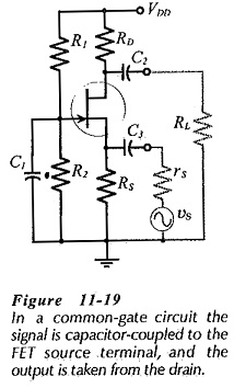
A fet amplifier circuit diagram is a series of diagrams that shows how an amplifier can be connected to an electronic device. While most people think of amplifiers as being associated with large audio systems, they also have other uses such as controlling the power supply of various applications. This type of circuit diagram can be used to build an amplifier that has the desired characteristics and is suited for the application.
An amplification circuit is essentially a series of components that form a connection between two points in a circuit. It is usually made up of transistors, resistors, diodes, and inductors. The way that these components are arranged will determine the output of the amplifier. The FET (Field-Effect Transistor) amplifier is a particular type of amplifier that has many advantages over the traditional amplifiers.
A FET amplifier circuit diagram will show how a FET can be connected to an electrical device. This type of amplifier is usually more efficient than traditional amplifiers, as it allows for more power when using fewer transistors and components. Additionally, it is capable of providing a higher gain, which allows it to be used in high-powered applications, such as amplifying sound signals from large speakers.
When constructing a FET amplifier circuit diagram, one must be sure to properly wire the components and connect them in the correct order. This requires knowledge of the connections and resistances of each component. Additionally, the level of power needed for the circuit should be established before constructing the diagram. It is important to adhere to the correct wiring procedures so that the amplifier can function correctly.
FET amplifiers have become more popular in recent years due to their versatility and cost efficiency. They are ideal for applications that require accurate adjustment of power levels, as they enable better control than traditional amplifiers. By using a FET amplifier circuit diagram, you can ensure that your amplifier will provide optimal performance for your specific application.

Basic Fet Amplifier Circuit Amplifiers Assignment Help

Fet Amplifier Circuit Rf Amplification

70 Watt Mosfet Audio Amplifier Circuit

Common Gate Circuit Equivalent Voltage Gain

Mosfets Basics Types Working Application Circuit
60 Watt Mosfet Audio Amplifier Red Page100

Cascode Amplifier Circuit Using Fets

Figure 3 51 Jfet Common Source Amplifier

The Basic Fet Amplifier Circuit A Under Other Circuits 60524 Next Gr

100w Mosfet Power Amplifier Circuit Using Irfp240 Irfp9240

Project 5 Buildaudioamps
2 Fet Amplifier Circuit And Miller Capacitance The Chegg Com

Simple Fet Circuits And Projects Homemade Circuit

Project 101 High Fidelity Lateral Mosfet Power Amplifier
Mosfet Amplifier Circuits

Solved 12 6 For The Mosfet Amplifier Circuit In Fig 5 Chegg Com

Solid State Circuits 1

Todays Circuits Engineering Projects Mosfet Amplifier
Solved Fet Amplifier Circuit And Miller Capacitance The Chegg Com

