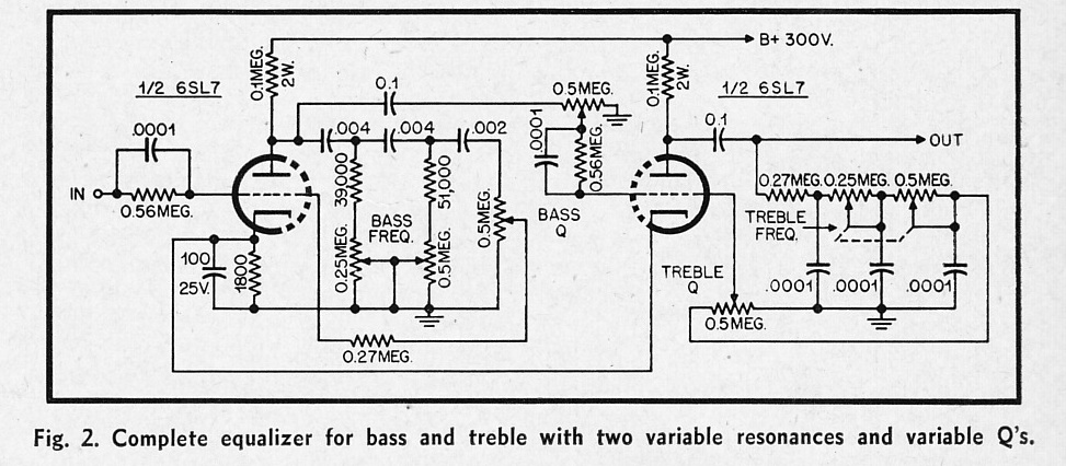
Welcome to the world of Eq Circuit Diagrams. If you’ve had even a passing experience with electronics, you’re probably familiar with the concept of circuit diagrams—those helpful diagrams used to represent and communicate electrical systems, circuits, and connections. But have you ever heard of Eq Circuit Diagrams?
Eq Circuit Diagrams are a type of circuit diagrams designed specifically to represent an equalizer system. An equalizer system is an electronic device used to modify, enhance, or otherwise manipulate the frequency spectrum of an audio signal. Equalizer systems can be used to help reduce unwanted background noise, as well as to increase desired sounds and effects.
So what sets Eq Circuit Diagrams apart from regular circuit diagrams? Essentially, they use special symbols, notations, and graphical elements to accurately depict the relationships between certain components of the equalizer system, including filters, amplifiers, and attenuators. This allows for a much more complex representation of the system than a traditional circuit diagram could provide, making it easier for technicians to understand and troubleshoot issues quickly.
To make use of Eq Circuit Diagrams, all you need to do is find an appropriate example of one. Fortunately, there are plenty of resources online that display these types of diagrams. Not only do these diagrams help technicians and engineers troubleshoot and modify equalizer systems more easily, but they can also be incredibly helpful to hobbyists. With Eq Circuit Diagrams, anyone can now build their own equalizer system and get it working just right.
From engineers and technicians, to hobbyists and audiophiles, Eq Circuit Diagrams are a useful and powerful tool. With these diagrams, it’s now easier than ever to modify and troubleshoot equalizer systems—allowing us to create better sound quality in our home theaters, recording studios, and beyond.

Audio Equalizer Tone Control Circuit With Bass Treble And Mid Frequency Using Op Amp

Tl074 10 Band Graphic Equalizer Schematic Circuit Circuits Elektropage Com

Electro Harmonix Graphic Equalizer Electronic Schematic Diagram
Design Note 92 An Adjule Cable Equalizer Analog Devices

Implement An Audio Frequency Tilt Equalizer Filter Edn

3 Band Graphic Equalizer Circuit Eeweb

Proto Pedal Example Analog Equalizer Project Learn Sparkfun Com

How To Build Your Own Audio Equalizer

Choices For A Simple Transpa 5 To 10 Band Eq Vocals

3 Band Audio Equalizer Circuit

Audio Graphic Equalizer Circuit
3 Band Eq Multisim Live

Energies Free Full Text A Cost Effective Passive Active Hybrid Equalizer Circuit Design

Graphic Equalizer Circuits With Pcb Layout For You Eleccircuit Com

Equalizer Circuit Page 2 Audio Circuits Next Gr

Stereo Vacuum Studio Eq Based On 1955 Circuit Preservation Sound

Circuit Diagram And Phase E Representation For The Chen Eq 8 Scientific

Pultec Equalizer Schematic Peatix

Advanced Mixer Circuits
Mxr 6 Band Eq Circuitlab
