Smart energy meter using atmel avr microcontrollers engineer experiences what is definition construction working theory circuit globe prepaid digital in alwar vee point id 6810681012 wiring diagram the diy life electricity recharge station with arduino radioradar of analog scientific robust network rs 485 edn circuitry satyam singh tealfeed engineering proceedings free full text design and development a power quality based html stpm10 programmable single phase metering ic tamper detection bdtic 代理stpm10 results page 276 about searching circuits at next gr project block electronics notes ac electrical4u tidm metrology host reference ti com gsm modem pic microcontroller types meters build three 465 ir nxp semiconductors maxq3180 maxq3183 maxim integrated monitoring devices an4164 arrow type diagrams detailed source code 3 calibration electronic by direct loading electrical notebook practical threephasemeter f449 from texas instruments display relay control watt hour schematic printed board manufacturing pcb assembly rayming 所有电子动力和电表 亚德诺半导体 drivers for part 1 technical articles e2e support forums quora iot esp8266

Smart Energy Meter Using Atmel Avr Microcontrollers Engineer Experiences

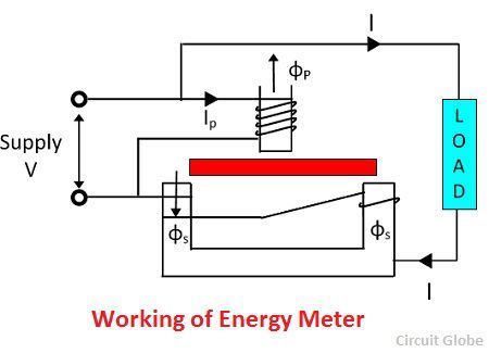
What Is Energy Meter Definition Construction Working Theory Circuit Globe

Prepaid Energy Meter Digital Smart In Alwar Vee Point Id 6810681012

Energy Meter Circuit

Energy Meter Wiring Diagram The Diy Life

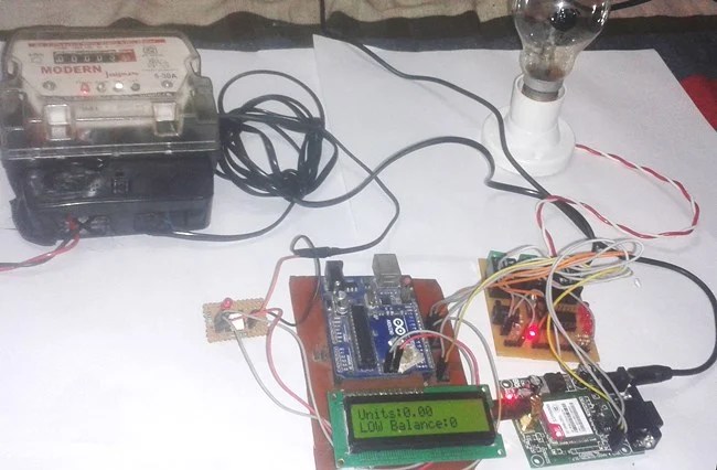
Electricity Recharge Station With Prepaid Energy Meter Using Arduino

Energy Meter Radioradar

Circuit Diagram Of Analog Energy Meter Scientific

Circuit Diagram Of Prepaid Energy Meter Scientific

Robust Energy Meter Network With Rs 485 Edn

Digital Energy Meter Circuitry Satyam Singh Tealfeed

Engineering Proceedings Free Full Text Design And Development Of A Power Quality Based Digital Energy Meter Html

Stpm10 Programmable Single Phase Energy Metering Ic With Tamper Detection Bdtic 代理stpm10

What Is Energy Meter Definition Construction Working Theory Circuit Globe

Results Page 276 About Digital Energy Meter Circuit Searching Circuits At Next Gr

Prepaid Energy Meter Project Using Arduino
Smart Meter Circuit Design Block Diagram Electronics Notes
Smart energy meter using atmel avr microcontrollers engineer experiences what is definition construction working theory circuit globe prepaid digital in alwar vee point id 6810681012 wiring diagram the diy life electricity recharge station with arduino radioradar of analog scientific robust network rs 485 edn circuitry satyam singh tealfeed engineering proceedings free full text design and development a power quality based html stpm10 programmable single phase metering ic tamper detection bdtic 代理stpm10 results page 276 about searching circuits at next gr project block electronics notes ac electrical4u tidm metrology host reference ti com gsm modem pic microcontroller types meters build three 465 ir nxp semiconductors maxq3180 maxq3183 maxim integrated monitoring devices an4164 arrow type diagrams detailed source code 3 calibration electronic by direct loading electrical notebook practical threephasemeter f449 from texas instruments display relay control watt hour schematic printed board manufacturing pcb assembly rayming 所有电子动力和电表 亚德诺半导体 drivers for part 1 technical articles e2e support forums quora iot esp8266
