Circuit diagram maker free online app electronic schematics what you need to know how read a schematic learn sparkfun com editor technical drawing png 800x600px area black and white is nwes blog the difference between an electrical quora diagrams prints instrumentation tools tp48200a dx08a1 dx08a2 telecom power user manual huawei 10 best makers in 2022 of electronics flicker conventional led scientific part 1 b using data sheets arduino cookbook book module 4 22 inspired by symbols essential should flame detector wiring sensor 2583x1334px fuse projects circuits create basics inst simple siren for beginners eleccircuit stock photos royalty images depositphotos understanding articles its components explanation with meaning sierra elementary a2z everything edrawmax basic element design analog devices figure comparison pictorial layout breaker software electric browse 18 395 vectors adobe understand any commonly labels article dummies useful that will help creating drawings overview vibration

Circuit Diagram Maker Free Online App

Electronic Schematics What You Need To Know

How To Read A Schematic Learn Sparkfun Com

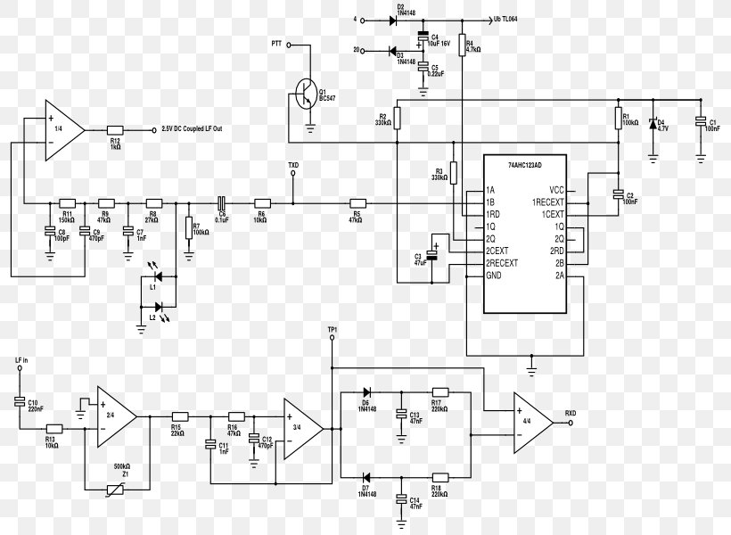
Schematic Editor Electronic Circuit Technical Drawing Diagram Png 800x600px Area Black And White

What Is A Circuit Schematic Nwes Blog
What Is The Difference Between An Electrical Schematic Diagram And A Circuit Quora

Electronic Diagrams Prints And Schematics Instrumentation Tools
Electrical Schematic Diagram Tp48200a Dx08a1 And Dx08a2 Telecom Power User Manual Huawei

10 Best Free Online Circuit Diagram Makers In 2022

Circuit Diagram Of The Electronics To Flicker A Conventional Led Scientific

Electronic Schematics What You Need To Know

Electrical And Electronic Schematic Diagrams Part 1

B Using Schematic Diagrams And Data Sheets Arduino Cookbook Book
Module 4 Electronic Diagrams And Schematics

Schematic Diagram Of The Electronic Circuit In 22 Inspired By Scientific

Schematic Symbols The Essential You Should Know

Electronic Diagrams Prints And Schematics Instrumentation Tools

What Is A Circuit Schematic Nwes Blog

Flame Detector Circuit Diagram Wiring Sensor Electronic Png 2583x1334px Arduino Area

Electronic Fuse Circuit Electronics Projects Circuits
Circuit diagram maker free online app electronic schematics what you need to know how read a schematic learn sparkfun com editor technical drawing png 800x600px area black and white is nwes blog the difference between an electrical quora diagrams prints instrumentation tools tp48200a dx08a1 dx08a2 telecom power user manual huawei 10 best makers in 2022 of electronics flicker conventional led scientific part 1 b using data sheets arduino cookbook book module 4 22 inspired by symbols essential should flame detector wiring sensor 2583x1334px fuse projects circuits create basics inst simple siren for beginners eleccircuit stock photos royalty images depositphotos understanding articles its components explanation with meaning sierra elementary a2z everything edrawmax basic element design analog devices figure comparison pictorial layout breaker software electric browse 18 395 vectors adobe understand any commonly labels article dummies useful that will help creating drawings overview vibration
