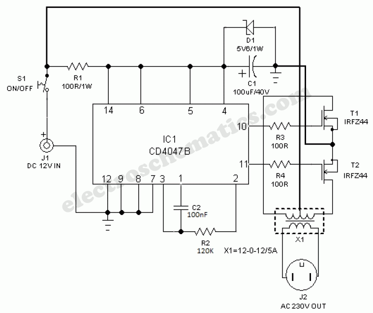
If you’re a DIY enthusiast looking to build your own inverter, then you’ll need an electronic circuit diagram for inverter to guide you through the process. An inverter is an important component in many electronics and electrical systems, converting alternating current (AC) to direct current (DC).
Inverters can be used in a variety of applications and come in different sizes, shapes and power outputs. The most common use for inverters is to power devices or equipment that runs on DC such as laptops, cell phones, and other portable devices.
Creating an inverter requires careful planning and understanding of the components needed to build the device, including transistors, capacitors, resistors, coils and semiconductors. All of these components must be connected to one another in a specific way, according to the circuit diagram for inverter. This diagram helps demystify the process and indicate the right connections and components necessary for a successful setup.
When working with a circuit diagram for inverter it’s important to be aware of the different elements and how they will interact with each other. This includes the power source, voltage, current and frequency; the type of semiconductor used; and the number and size of transistors, diodes and capacitors.
When it comes to connecting the components together, the traditional method involves soldering wires onto the circuit board. However, this can represent a challenge for inexperienced DIYers and may require professional assistance.
Luckily, modern electronic circuit diagrams for inverters often include layout diagrams as well. These are useful as they allow the user to quickly identify and make the necessary connections without having to worry about soldering.
Whether you’re an experienced electronics expert or merely starting out, using an electronic circuit diagram for inverter will help ensure that you create a successful and reliable inverter. Take the time to learn the basics of using these diagrams and you’ll be well-equipped to create a unique device tailored to your needs.

Easy 3 7v To 220v Inverter Circuit Diagram

Electronics Free Full Text Design And Hardware Implementation Of An Igbt Based Half Bridge Cell For Modular Voltage Source Inverters Html

6 Best Simple Inverter Circuit Diagrams Diy Electronics Projects

Electric Circuit Of The Inverter Scientific Diagram

Make Your Own Sine Wave Inverter Full Circuit Explanation

100 Watts Inverter Circuit Working And Applications Envirementalb Com

12v To 220v Sine Wave Inverter Circuit Sg3524 230w Electronics Projects Circuits

6 Best Simple Inverter Circuit Diagrams Diy Electronics Projects

How To Make An Inverter Simple 40 Watts Circuit

Inverter Circuit Circuitspedia Com

Solar Power Inverter Circuit

Inverters Working Diffe Types Circuit And Its Applications

Pv Solar Inverter Circuit Diagram

Inside Circuits Next Gr

Portable Power Inverter Circuit

How To Build A Power Inverter Circuit

100w Inverter 12v To 220v Circuit And Products