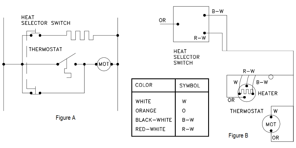
Electrical schematics and diagrams are essential when it comes to understanding how electricity works. From wiring your home to building a complex robotics project, these diagrams are used in all kinds of applications. But for the average person, they may look confusing, especially if you’ve never dealt with anything like them before. In this article, we’ll walk you through the basics of electrical schematics and diagrams so you can understand them better and use them more effectively.
Electrical schematics are a graphical representation of the components and connections that make up an electrical system. They provide detailed information about the way components interact and their relationship to each other. Schematics are typically drawn in an abstracted form, using lines, symbols, and numbers to represent physical elements, from resistors and transistors to power supplies and motors. This makes it easier for technicians and engineers to identify problems and fix them quickly.
Diagrams, on the other hand, are a more graphical representation of the same concept. Diagrams are usually used to illustrate how a particular system works by showing how each part is connected. For example, a diagram could show the connections between a battery, a motor, and a light bulb. Both schematics and diagrams are designed to help people understand the workings of complex systems.
Understanding electrical schematics and diagrams can be difficult at first, but with practice and patience, you can become a skilled user. With a good understanding of the basics, you’ll be able to troubleshoot effectively and build your own projects quickly and easily. Whether you’re a beginner or a seasoned professional, knowing how to read and interpret these diagrams will make you a more competent technician and engineer.

Reading Electrical Diagrams And Schematics

How To Create Circuit Diagram

European Schematics Control Parts

How To Read Car Wiring Diagrams For Beginners Emanualonline Blog

The Wiring Diagram And Physical Layout Of Equipment Inside Motor Control Centre Eep

Electrical Diagrams And Schematics Inst Tools

L2 Circuit Schematics Physical Computing

10 Best Free Online Circuit Diagram Makers In 2022

Electrical Drawings And Schematics Overview

Electrical Drawings And Schematics Overview

How To Create Circuit Diagram

Electrical Schematic Diagram Elementary Wiring A2z

Schematic Diagram Of Electrical Control 1 Scientific

How To Read And Understand An Electrical Schematic

Electrical Schematic Diagram Scientific

Electrical Schematic Symbols Input Devices Petroed

Introduction To Electrical Schematics Petroed

Marine Electrical Diagram Single Line Etap