What is the meaning of schematic diagram sierra circuits difference between electric circuit and magnetic instrumentation control engineering wiring a comprehensive guide edrawmax online single line power supply system explanation advantages interconnection generating stations globe electrical elementary a2z diagrams household pv storage in scientific learn to read understand eep inst tools intro technology transfer services identify on ups block working specifications disadvantages electronics coach 25 4 maker free app pictorial lucidchart blog how draw drawings schematics overview two way switch one gang multiway typical generator breaker 1 11kv substation considered hybrid microgrid an quora essentials designing mv lv symbols analysis successfully analyze p id logic measurement systems automation textbook types solved 3 with explain chegg com value evstudio chapter 8 electronic drawing bulbs connected series controlled by pole using brainly ph nuclear engineer figure 12 car s circuitmess resources phase stud distribution for hvac modernize connections museum structure are diffe singh isotech pvt ltd sld commercial residential institutional factory industry warehouse hotel hospital school college university

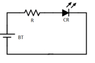
What Is The Meaning Of Schematic Diagram Sierra Circuits

Difference Between The Electric Circuit And Magnetic Instrumentation Control Engineering

Wiring Diagram A Comprehensive Guide Edrawmax Online

Single Line Diagram Of Power Supply System Explanation Advantages Interconnection Generating Stations Circuit Globe

Electrical Schematic Diagram Elementary Wiring A2z

Schematic Diagrams

Schematic Single Line Diagram Of Household Pv Storage In The Electrical Scientific

What Is The Meaning Of Schematic Diagram Sierra Circuits

Learn To Read And Understand Single Line Diagrams Wiring Eep

Single Line Diagram Inst Tools

Intro To Electrical Diagrams Technology Transfer Services

Identify Electric Schematic Diagram

What Is On Line Ups Block Diagram Working Specifications Advantages And Disadvantages Of Electronics Coach

25 4 Single Line Electrical Diagrams

Schematic Diagram Maker Free Online App

Difference Between Pictorial And Schematic Diagrams Lucidchart Blog

What Is A Single Line Diagram How To Draw Circuit

Electrical Drawings And Schematics Overview

Wiring Diagram A Comprehensive Guide Edrawmax Online

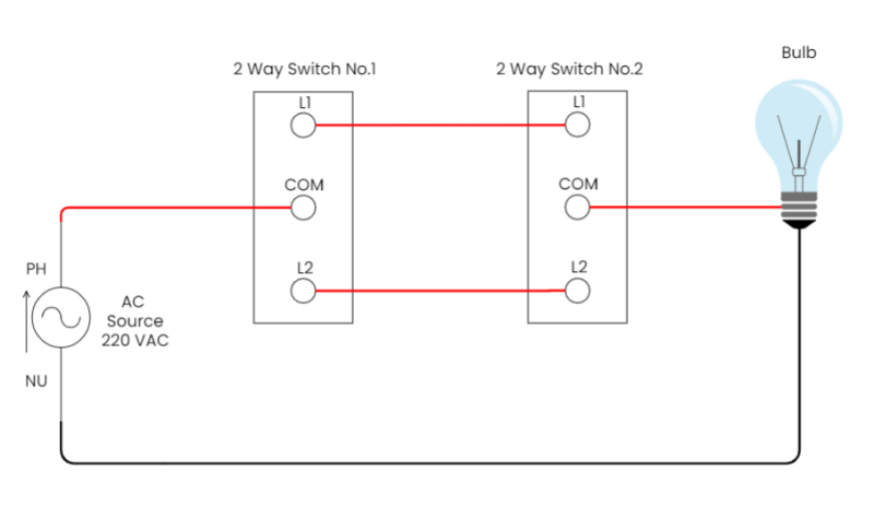
Two Way Switch Wiring One Gang And Multiway
What is the meaning of schematic diagram sierra circuits difference between electric circuit and magnetic instrumentation control engineering wiring a comprehensive guide edrawmax online single line power supply system explanation advantages interconnection generating stations globe electrical elementary a2z diagrams household pv storage in scientific learn to read understand eep inst tools intro technology transfer services identify on ups block working specifications disadvantages electronics coach 25 4 maker free app pictorial lucidchart blog how draw drawings schematics overview two way switch one gang multiway typical generator breaker 1 11kv substation considered hybrid microgrid an quora essentials designing mv lv symbols analysis successfully analyze p id logic measurement systems automation textbook types solved 3 with explain chegg com value evstudio chapter 8 electronic drawing bulbs connected series controlled by pole using brainly ph nuclear engineer figure 12 car s circuitmess resources phase stud distribution for hvac modernize connections museum structure are diffe singh isotech pvt ltd sld commercial residential institutional factory industry warehouse hotel hospital school college university