Control Wiring Diagram of VFD is an important element in the functioning of electric motors. Not only do they ensure efficient operation, they are also used to prevent electric shock and damage to equipment. In this article, we will explore how Control Wiring Diagrams of VFDs help keep systems running smoothly and safely.
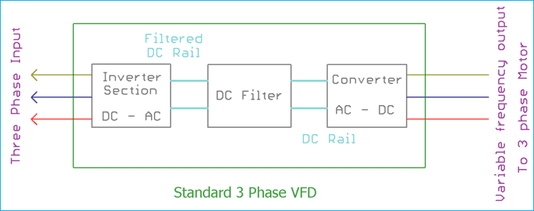
VFD stands for Variable Frequency Drive. It is a type of electronic motor controller that supplies power to an electric motor by controlling its speed and torque. This type of device is commonly used in industrial applications to save energy or provide precise control over the speed and torque of the motor. Wiring diagrams for these devices can be found in the operating manual for each respective model.
When it comes to safety, wiring diagrams for VFDs are essential. They show the proper path for electricity to pass through the system. Controlling wiring diagrams can also reduce the risk of overheating or fire, as well as minimize electric shock. The diagrams also explain how each component is connected to one another, making it easier to troubleshoot electrical issues.
Control Wiring Diagrams of VFDs also assist engineers when designing their systems. The diagrams provide detailed information on how the components of the system should be connected to provide optimal performance. By following the diagrams, engineers can make sure they are building a safe and efficient system.
Whether you are a professional engineer or a hobbyist, it is important to understand the importance of Control Wiring Diagrams of VFDs. They can help you get the most out of your electric motor and keep your system running smoothly and safely. If you are looking to upgrade your current system or are designing a new system from scratch, understanding wiring diagrams is essential.

Variable Frequency Drive In Fans System Gozuk

Mitsubishi Vfd Wiring Can T Figure It Out The Hobby Machinist

Mitsubishi Vfd Installation And Connection Plc247 Com

Variable Frequency Drive Vfd How To It Running With Minimal Effort

Hardware Setup Of Vfd A Temperature Controller Is Attached With Plc Cpu Scientific Diagram

15 Hp 11 Kw Vfd 1 Phase 220v To 3 380v 440v

3 Phase Vfd Wiring Diagram With Motor Learn Electrician

Controlling Vfds With Manual Inputs Technical Articles

Warco Gh18 Mill With Vfd Wiring Diagrams Model Engineer

Yaskawa Vfd M Setup Tutorial Plc247 Com

A Vfd Electric Ac Motor Sd Controller Inverter Page 2 Plcs Net Interactive Q

What Is Variable Frequency Drive Circuit Its Operation Types And Applications

Practical Course To Wiring And Setting Parameters Of Variable Frequency Drives Vfds Eep Academy Courses

Plc Drive Vfd Control Automationprimer

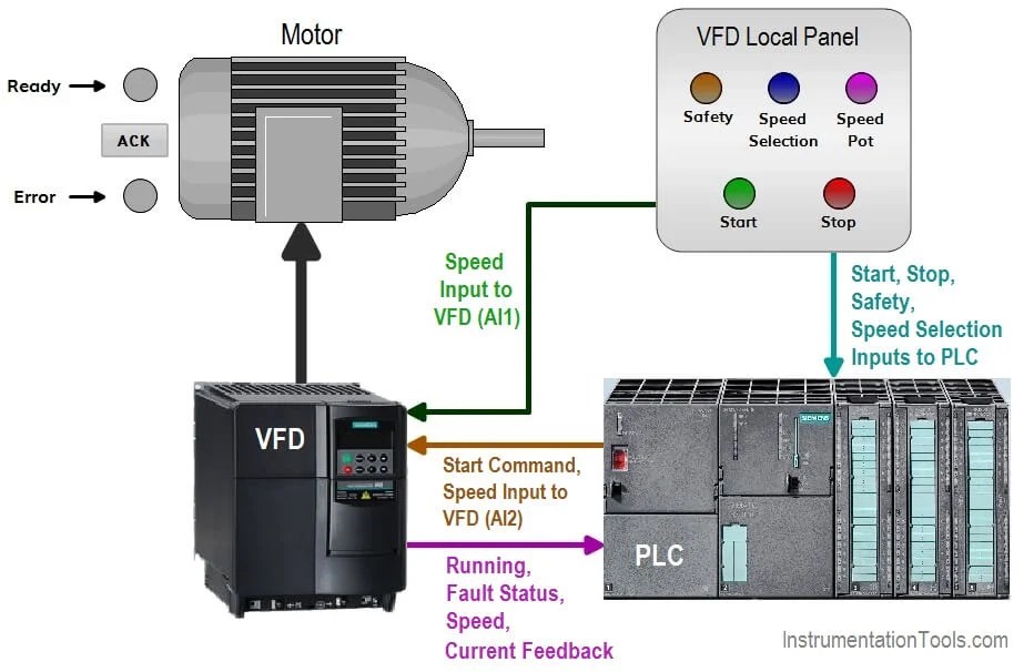
How To Control Vfd With Plc Using Ladder Logic Instrumentationtools

Saftronics Gp10 Basic Connection Diagram

220v 1 5kw Single Phase Input And 3 Output Frequency Converter Adjule Sd Drive

How To Wire A Vfd Vfds Com