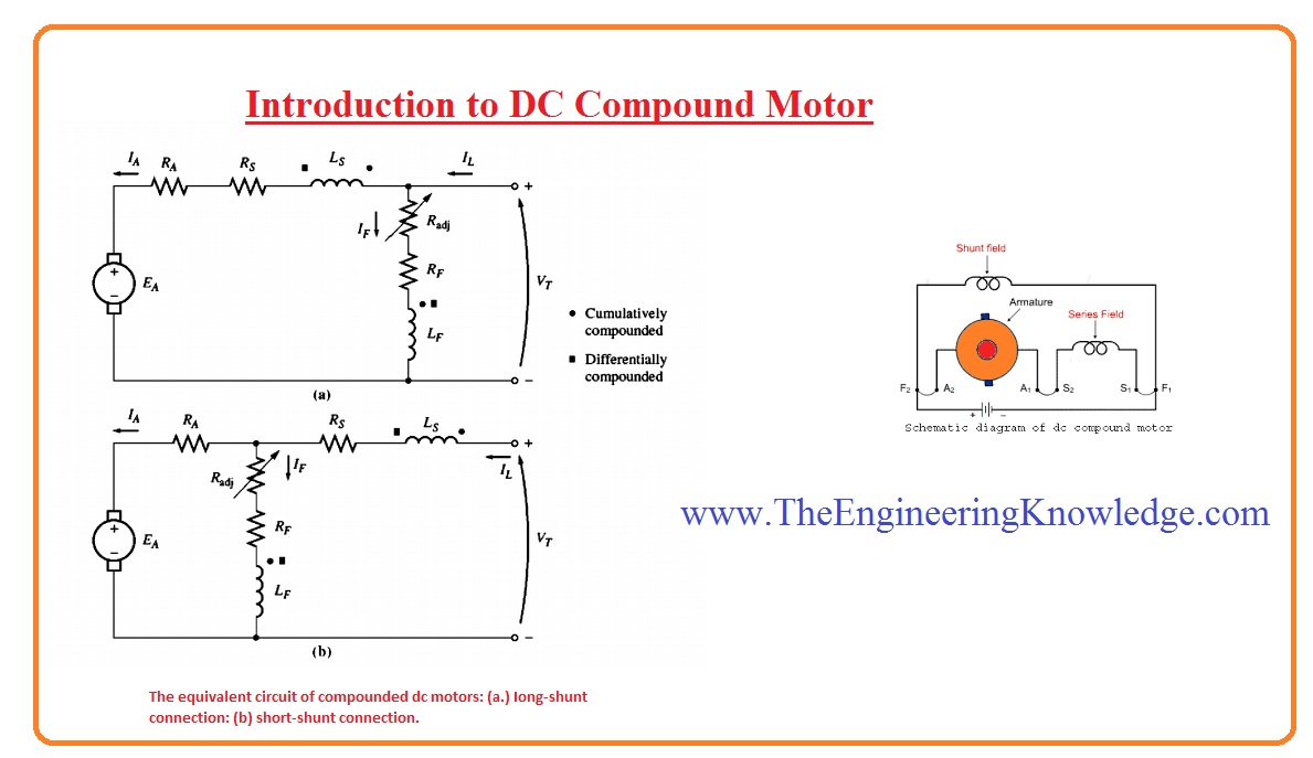
We'll never be able to understand the full potential of our electronics if we don't understand how their components work. That's why it's important to familiarize yourself with the basics: a compound DC motor schematic diagram. This diagram shows the way that electric current flows through different parts of the system to create a specific type of motor.
A compound DC motor is an electromechanical device that converts electrical energy into mechanical power. It consists of two or more windings on a rotor and stator, along with commutators, brushes, and other components.
The main use of a compound DC motor is to control the motion of a machine, or to run a load with precision. Many industries, such as robotics and automation, rely heavily on these motors.
The schematic diagram of the compound DC motor is fairly straightforward. The first component is the stator, which is a stationary coil of wire. The rotor is then placed in the center of the stator and turns on its own axis. The two components are connected to a source of electricity. As the current passes through the windings, it creates a magnetic field that causes the rotor to rotate.
The next part of the motor is the commutator. This is a rotating contact arm that switches between two sets of contacts, allowing for the current to flow in either direction. The brushes ensure that the current is always applied to the right spot on the commutator.
Finally, the speed of the motor is regulated by the armature, which is a circular wire coil that creates the torque needed to turn the rotor. All of these components must be arranged correctly to make sure that the motor works properly.
Understanding the compound DC motor schematic diagram will help you understand how your electronics work and how they can be controlled. By familiarizing yourself with these diagrams, you'll have a better understanding of how to design and troubleshoot electronics projects.

Types Of Dc Motor Shunt Series Compound Wound Circuit Globe

Design Of Low Power Dc Motors Shunt Wound Series Compound Motor Automotive Systems

Types Of Dc Motor Your Electrical Guide

Principle Scheme Of Compound Dc Motor Scientific Diagram

Dc Motor Types Shunt Series Compound Permanent Magnet Electrical A2z

Sd Control Of Dc Motor Shunt Series Electrical4u

Dc Compound Motors

Compound Wound Dc Motor Or The Engineering Knowledge

Shunt Motor An Overview Sciencedirect Topics

Dc Motor Starters And Their Circuit Diagram Electrical Academia

D C Compound Motor Electrical Engineering Interview Questions

Draw The Diagram Of Series Motor Bartleby

Types Of Dc Motors And Their Characteristics Electrical Academia

Types Of Dc Motor Steadt State Equivalent Circuit Moving Coil Motors

Dc Motor Types Shunt Series Compound Permanent Magnet Electrical A2z

What Are Wound Field Motors And Where They Applied

Sd Control Of A Dc Compound Motor

Dc Motor Connections Inst Tools

Compound Wound Dc Motor Calculations Electric Motors