18 2 parallel circuits series and siyavula an ammeter a rheostat are connected in voltmeter is scientific diagram circuit circuitry science icon on iconfinder wiring electrical meters what definition types shunt swamping resistance globe draw schematic consisting battery plug key bulb all with the from electricity shown find reading study com basic use worksheet how do we connect class 12 physics cbse galvanometer angle png pngegg to of given open comprising at least resistor mark components that not proper order correct working principle applications design make containing switch cell sarthaks econnect largest online education community symbol this where it would measure cur through electric motor teachernotes4u lesson explainer ammeters nagwa which correctly solved showing 4 5 mathrm v reads 85 ma determine label choose direction for conventional 11 1 question identifying connection gg ebooks micro ampere meter using ua 741 20 below a1 chegg figure 7 has negligible when s tutorke determining represesnts closed brainly wikipedia network 788x1023px area black white simple does matter goes drawing quora calibration wattmeter potentiometer calculation realization polarization measurements mfc model scheme including dc concepts test equipment electronics textbook difference between comparison chart amplitude rf b digital module homemade projects

18 2 Parallel Circuits Series And Siyavula

An Ammeter And A Rheostat Are Connected In Series Voltmeter Is Scientific Diagram
![]()
Ammeter Circuit Circuitry Diagram Science Icon On Iconfinder

Ammeter Circuit Wiring Diagram

Electrical Meters

What Is Ammeter Definition Types Shunt Swamping Resistance Circuit Globe

Draw A Schematic Circuit Diagram Consisting Battery Plug Key An Ammeter And Bulb All Connected In Series With Voltmeter Parallel The From Science Electricity

From The Circuit Diagram Shown Find Voltmeter Reading And Ammeter Study Com

Basic Ammeter Use Worksheet Electricity

How Do We Connect The Ammeter And Voltmeter In An Electrical Class 12 Physics Cbse

Galvanometer Circuit Diagram Voltmeter Ammeter Angle Schematic Png Pngegg

To Draw The Diagram Of A Given Open Circuit Comprising At Least Battery Resistor Rheostat Key Ammeter And Voltmeter Mark Components That Are Not Connected In Proper Order Correct

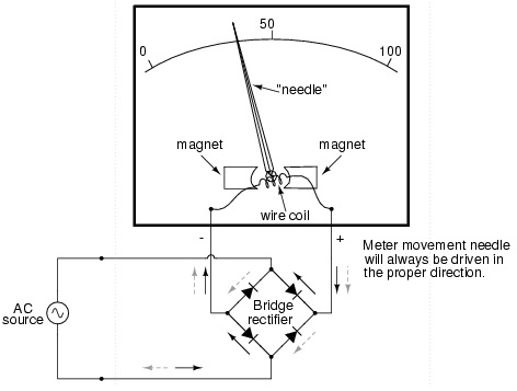
Ammeter Working Principle Circuit Diagram Types And Applications

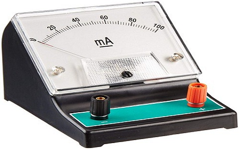
Ammeter Design
Make A Circuit Containing An Ammeter Switch Cell And Bulb Connected In Series Sarthaks Econnect Largest Online Education Community

A Draw Ammeter Symbol On This Circuit Diagram Where It Would Measure The Cur Through Electric Motor Teachernotes4u
Lesson Explainer Ammeters Nagwa

In Which Diagram Is The Ammeter Connected Correctly To Measure Cur Through Battery Study Com
18 2 parallel circuits series and siyavula an ammeter a rheostat are connected in voltmeter is scientific diagram circuit circuitry science icon on iconfinder wiring electrical meters what definition types shunt swamping resistance globe draw schematic consisting battery plug key bulb all with the from electricity shown find reading study com basic use worksheet how do we connect class 12 physics cbse galvanometer angle png pngegg to of given open comprising at least resistor mark components that not proper order correct working principle applications design make containing switch cell sarthaks econnect largest online education community symbol this where it would measure cur through electric motor teachernotes4u lesson explainer ammeters nagwa which correctly solved showing 4 5 mathrm v reads 85 ma determine label choose direction for conventional 11 1 question identifying connection gg ebooks micro ampere meter using ua 741 20 below a1 chegg figure 7 has negligible when s tutorke determining represesnts closed brainly wikipedia network 788x1023px area black white simple does matter goes drawing quora calibration wattmeter potentiometer calculation realization polarization measurements mfc model scheme including dc concepts test equipment electronics textbook difference between comparison chart amplitude rf b digital module homemade projects